X-ray tube cathode with reduced unintended electrical field emission

a cathode and x-ray tube technology, applied in the field of x-ray tube sources, can solve the problems of compromising performance, taking no particularly effective measure, and electric arcing between the opposing electrodes, and achieve the effect of reducing adverse triple point-related phenomena, better focus and control of electron beams, and improving the performance of the device as an x-ray sour

Active Publication Date: 2007-04-05
MOXTEK INC
View PDF44 Cites 31 Cited by
  • Summary
  • Abstract
  • Description
  • Claims
  • Application Information

AI Technical Summary

Benefits of technology

[0010] It has been recognized that it would be advantageous to develop cathode element for use in a mobile, miniature x-ray source that locates the triple point interface out of the region of highest electric fields to prevent arcing between the cathode and anode electrodes and the generation of extraneous, field-emitted charge. Additionally, it has been recognized that it would be advantageous to develop a cathode element for a mobile, miniature x-ray source that would manage flow of the braze material, used to physically join the metallic electrode to the dielectric insulator, in order to minimize adverse triple point-related phenomena. It has also been recognized that it would be advantageous to develop a vacuum tube for a mobile, miniature x-ray source that would provide better focus and control of the electron beam, thereby offering better performance of the device as an x-ray source.

Problems solved by technology

Extremely high electric fields may exist upon certain features of the device, causing electrical arcing between the opposing electrodes.
Current miniature x-ray tube geometry places the triple point in a region subject to high electric field intensity, taking no particularly effective measure to avoid the aforementioned adverse effects.
Thus, arcing between the cathode and anode and unintended field emission are likely to occur, compromising the performance and shortening the life of the device as a whole.

Method used


Image

  • X-ray tube cathode with reduced unintended electrical field emission
  • X-ray tube cathode with reduced unintended electrical field emission
  • X-ray tube cathode with reduced unintended electrical field emission

Examples


Embodiment Construction

[0021] Reference will now be made to the exemplary embodiments illustrated in the drawings, and specific language will be used herein to describe the same. It will nevertheless be understood that no limitation of the scope of the invention is thereby intended. Alterations and further modifications of the inventive features illustrated herein, and additional applications of the principles of the inventions as illustrated herein, which would occur to one skilled in the relevant art and having possession of this disclosure, are to be considered within the scope of the invention.

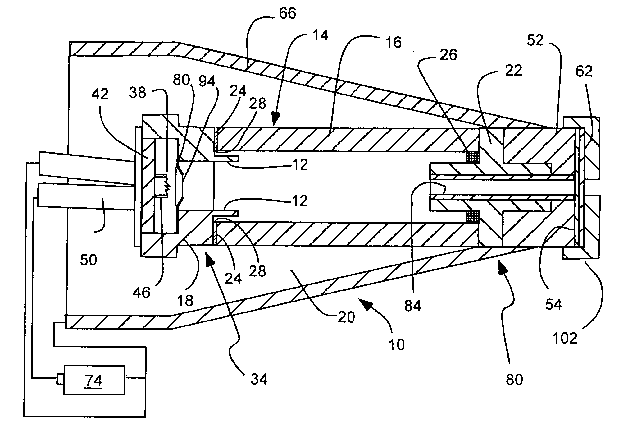
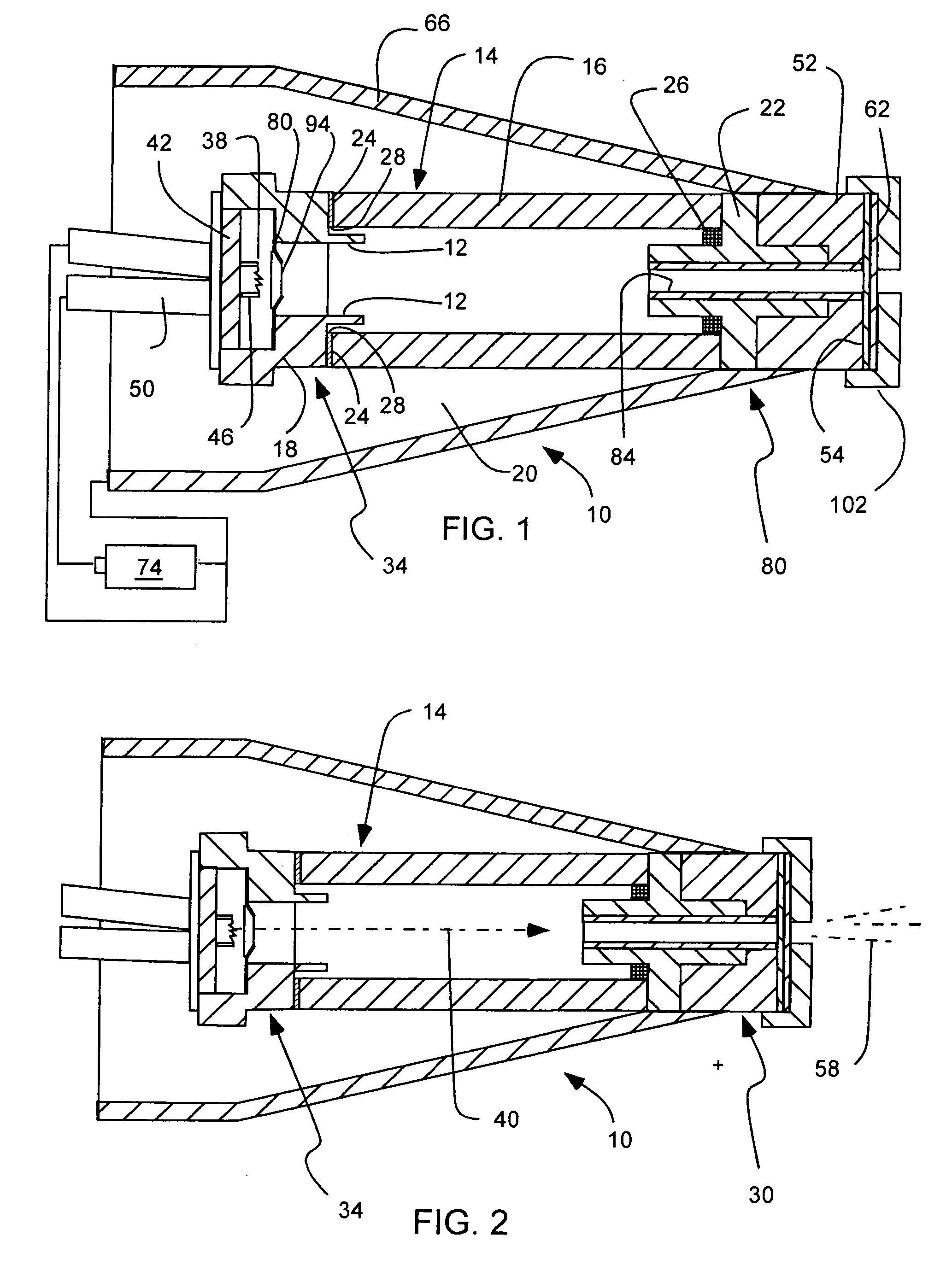
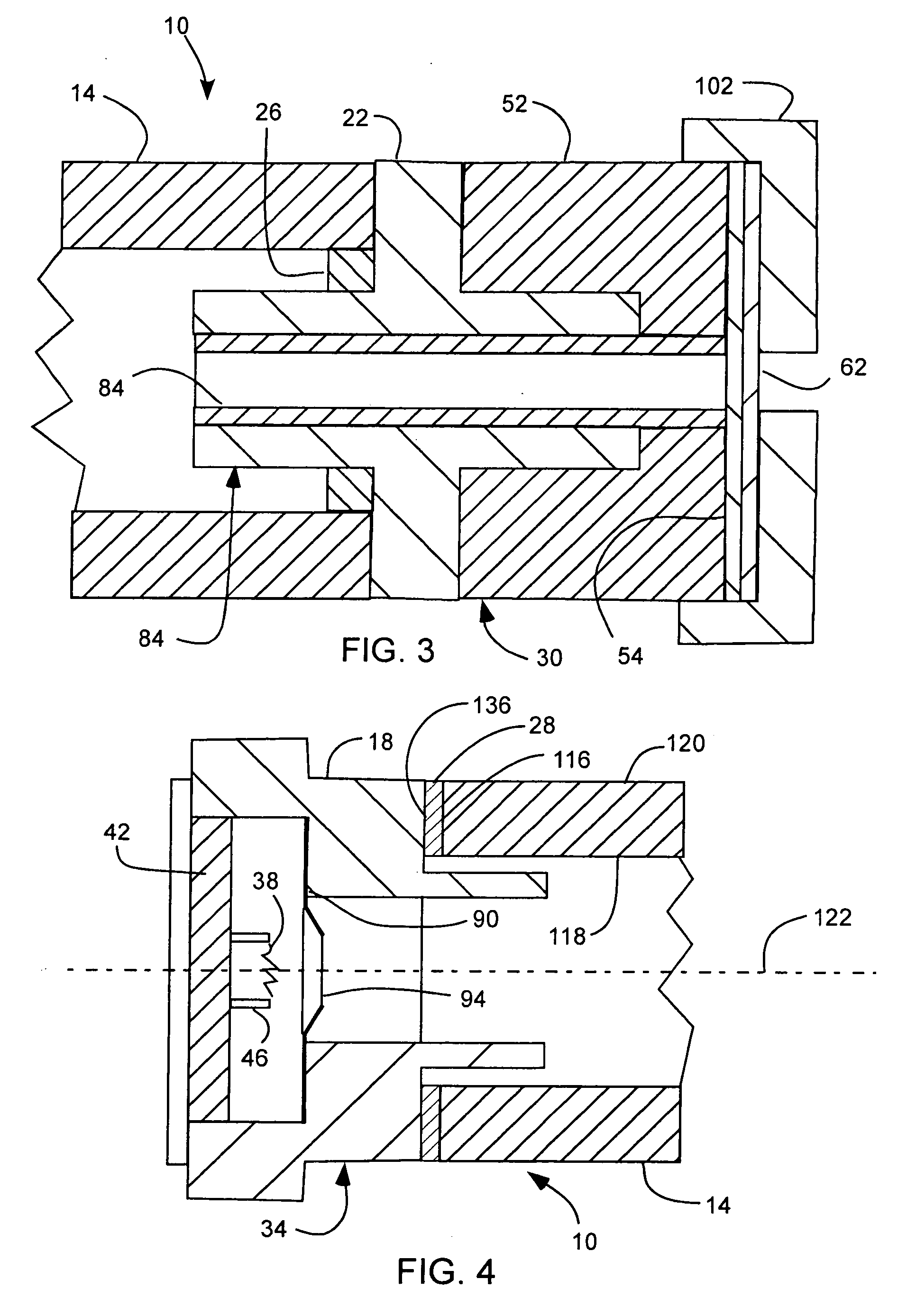
[0022] As illustrated in FIGS. 1-4, a mobile, miniature x-ray source, indicated generally at 10 is shown, in accordance with the present invention. Certain aspects of such an x-ray source are disclosed in U.S. Pat. Nos. 6,661,876 and 7,035,379, which are incorporated herein by reference. The x-ray source 10 can include a low power consumption cathode element suitable for use with a battery power source to allow...


PUM


Abstract

An x-ray source has an evacuated tube. An anode is disposed in the tube and includes a material configured to produce x-rays in response to impact of electrons. A cathode is disposed in the tube opposing the anode configured to produce electrons accelerated towards the anode in response to an electric field between the anode and the cathode. A flange extends from the cathode toward the anode, and has a smaller diameter than the evacuated tube. The flange extends closer to the anode than an interface between the cathode and the tube thus forming a reduced-field region between the evacuated tube and the flange.

Description

PRIORITY CLAIM [0001] Priority is claimed to U.S. Provisional Patent Application Ser. No. 60 / 722,738, filed on Sep. 30, 2005; which is herein incorporated by reference.BACKGROUND OF THE INVENTION [0002] 1. Field of the Invention [0003] The present invention relates generally to X-ray tube sources, such as mobile, miniature X-ray tube sources, and more particularly to the geometry of the cathode element used in a miniature X-ray tube to reduce unintended electrical field emissions. [0004] 2. Related Art [0005] In an X-ray tube, electrons emitted from a cathode source are attracted to an anode by the high bias voltage applied between these two electrodes. The intervening space must be evacuated to avoid electron slowing and scattering, and also to prevent ionization of containment gas and acceleration of the resulting ions to the cathode where they erode the filament and limit tube life. Characteristic and Bremsstrahlung X rays are generated by electron impact on the anode target mate...

Claims


Application Information

Patent Timeline
Patent Type & Authority Applications(United States)
IPC IPC(8): H01J35/00
CPCH01J35/14H01J35/18H01J2235/1216H01J35/186H01J35/147
Inventor BARD, ERIK C.JENSEN, CHARLES R.OGDEN, SHAUN P.LIDDIARD, STEVEN D.
Owner MOXTEK INC
Why Eureka
Try Eureka