Eureka AIR delivers breakthrough ideas for toughest innovation challenges, trusted by R&D personnel around the world.

Thin type micro reforming apparatus

Inactive Publication Date: 2007-04-05
SAMSUNG ELECTRO MECHANICS CO LTD
View PDF3 Cites 5 Cited by
  • Summary
  • Abstract
  • Description
  • Claims
  • Application Information

AI Technical Summary

Benefits of technology

[0016] An object of the present invention is to provide an improved thin type reforming apparatus with a differently structured evaporator that supplies fuel in the form of small droplets to increase the surface area of the fuel, so that when the same amount of fuel is vaporized, an increased evaporating efficiency can obtained by the present invention.
[0017] Another object of the present invention is to provide an improved thin type reforming apparatus that can effectively prevent reverse flow of supplied fuel due to back pressure.
[0018] A further object of the present invention is to provide an improved thin type reforming apparatus with an expanded and opened evaporator to accommodate the expansion of gas and substantially reduce back pressure from the evaporator to the fuel supply portion.
[0019] A still further object of the present invention is to provide an improved thin type reforming apparatus that has protrusions in the form of islands within the evaporator, in order to facilitate the removal of bubbles in the liquid fuel during evaporation of the fuel, for preventing a buildup of back pressure and increase heat transfer efficiency to efficiently vaporize liquid fuel and improve performance.
[0020] An additional object of the present invention is to provide an improved thin type reforming apparatus that supplies liquid fuel inside the evaporator in the form of droplets, so that easy vaporization of the fuel can be achieved without the formation of bubbles, preventing reverse flow of the liquid fuel caused by back pressure, and allowing overall miniaturization of the reforming apparatus.

Problems solved by technology

However, a reforming apparatus needs to be added to the system, making the device unsuitable for miniaturization.
Accordingly, not only is this conventional configuration of a reforming apparatus 250 complex, it is also difficult to miniaturize.
However, because the height of the fins 317 and the width of the passage must be formed in different dimensions, either dry etching must be performed twice or the manufacturing process becomes difficult.
However, in this conventional structure, although a passage extends from the evaporator 403, gas formation that occurs when liquid fuel is vaporized cannot be prevented.
Thus, in conventional reforming apparatuses, as fuel is vaporized in the evaporators, a sudden expansion occurs where bubbles are formed within the evaporator to increase pressure.

Method used


Image

  • Thin type micro reforming apparatus
  • Thin type micro reforming apparatus
  • Thin type micro reforming apparatus

Examples


Embodiment Construction

[0033] Reference will now be made in detail to the preferred embodiments of the present invention, examples of which are illustrated in the accompanying drawings.

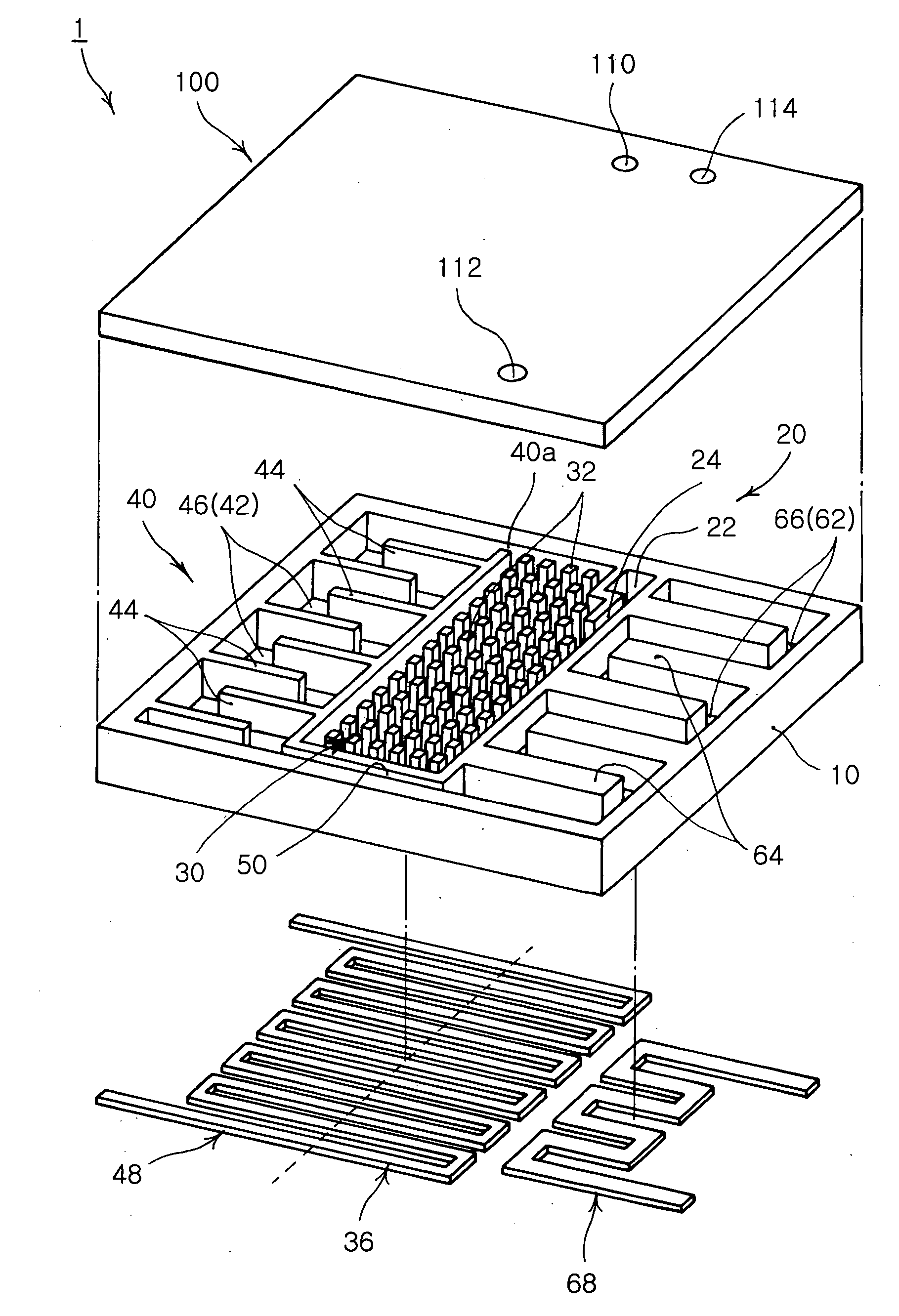
[0034] As shown in FIG. 4, a thin type reforming apparatus 1 according to an embodiment of the present invention includes a substrate 10 having a passage formed therein. The substrate 10 may be made of silicon, metal, glass, ceramic, and heat resistant plastic, and indented passages defined by partitions are formed in a regular manner through etching into one side of the substrate 10.

[0035] That is, etching is performed on one side of the substrate 10, forming a desired configuration of indented passages.

[0036] A fuel inlet 20 is provided to introduce fuel into the passages of the substrate 10. The fuel inlet 20, as shown in FIGS. 4 and 5, is formed at an approximate central location of the substrate 10. The passage 22 of the fuel inlet 20 is formed at one edge of the substrate 10, and leads to a narrow exit 24 to supply...


PUM


Abstract

A thin type reforming apparatus used for a fuel cell is provided. In the thin type reforming apparatus, a substrate has a passage formed therein, and a fuel inlet introduces fuel to the passage. An evaporator is disposed within the substrate downstream of the fuel inlet, and includes a bubble remover for imparting a flow resistance to the fuel in a liquid state, removing bubbles and vaporizing the fuel. A reformer has a passage formed downstream of the evaporator, and reforms the fuel to hydrogen gas through a heat absorbing reaction. A CO remover has a passage formed downstream of the reformer and removes CO gas included in the hydrogen gas through a heat radiating reaction. A cover covers an upper portion of the substrate and sealing the passages from an outside.

Description

RELATED APPLICATION [0001] The present application is based on, and claims priority from, Korean Application Number 2005-92065, filed Sep. 30 2005, the disclosure of which is hereby incorporated by reference herein in its entirety. BACKGROUND OF THE INVENTION [0002] 1. Field of the Invention [0003] The present invention relates to a thin type micro reforming apparatus used in a fuel cell, and more particularly, to an improved thin type micro reforming apparatus having a bubble remover in the evaporator to effectively remove bubbles formed during the vaporizing of liquid fuel, in order to prevent a pressure buildup within the evaporator and increase heat transfer efficiency. The improved thin type micro reforming apparatus also supplies liquid fuel in the form of droplets to be vaporized in the evaporator, thereby to prevent reverse flow caused by back pressure of the liquid fuel. [0004] 2. Description of the Related Art [0005] A recent increase in the use of mobile phones, PDAs, dig...

Claims


Application Information

Patent Timeline
IPC IPC(8): B01J10/00B01J8/04
CPCC01B3/323B01J2219/00873C01B2203/044C01B2203/047C01B2203/066C01B2203/085C01B2203/1041C01B2203/1047C01B2203/107C01B2203/1076C01B2203/1223C01B2203/1258C01B2203/1288B01J19/0093B01J2219/00783B01J2219/00835C01B2203/0233C01B3/38
Inventor GIL, JAE HYOUNGJANG, JAE HYUKKIM, SANG JINKIM, SUNG HAN
Owner SAMSUNG ELECTRO MECHANICS CO LTD
Why Eureka
Eureka Blog
Learn More