Reinforced membrane electrode assembly

a membrane electrode and reinforcement technology, applied in the field of electrochemical conversion cells, can solve the problems of low crossover rate, low gas crossover rate, localized heating and integrity loss in the membrane, etc., and achieve the effect of reducing crack driving force, crack open area, and reducing reaction gas crossover leakag

Inactive Publication Date: 2007-04-05
GM GLOBAL TECH OPERATIONS LLC
View PDF5 Cites 14 Cited by
  • Summary
  • Abstract
  • Description
  • Claims
  • Application Information

AI Technical Summary

Benefits of technology

[0002] The present invention is directed to addressing performance issues attributable to membrane electrode assemblies, and the components thereof, in electrochemical conversion cells. More specifically, the present invention is directed to the addition of one or more external reinforcement layers to the membrane electrode assembly (MEA) of electrochemical conversion cells. With the addition of the external reinforcement layer, the reactant gas crossover leak can be reduced by reducing crack driving force and crack open area associated with mechanical stresses induced during thermal and hydro cycling in the cell.

Problems solved by technology

In the extreme case, as is often observed when PEM cells reach the end of their service life, pinhole formation leads to localized heating and integrity loss in the membrane.
Typically, gas crossover rates are initially low but slowly increase over the fuel cell service life.
At this stage, cracks are usually short and barely open which leads to low crossover rate.
As the membrane goes through a significant number of thermal and hydration cycles, accumulated fatigue damage in the material sets the stage for crack propagation.
More rapid crack growth is accompanied by an accelerated increase in gas crossover rate, hastening membrane failure.

Method used


Image

  • Reinforced membrane electrode assembly
  • Reinforced membrane electrode assembly
  • Reinforced membrane electrode assembly

Examples


Embodiment Construction

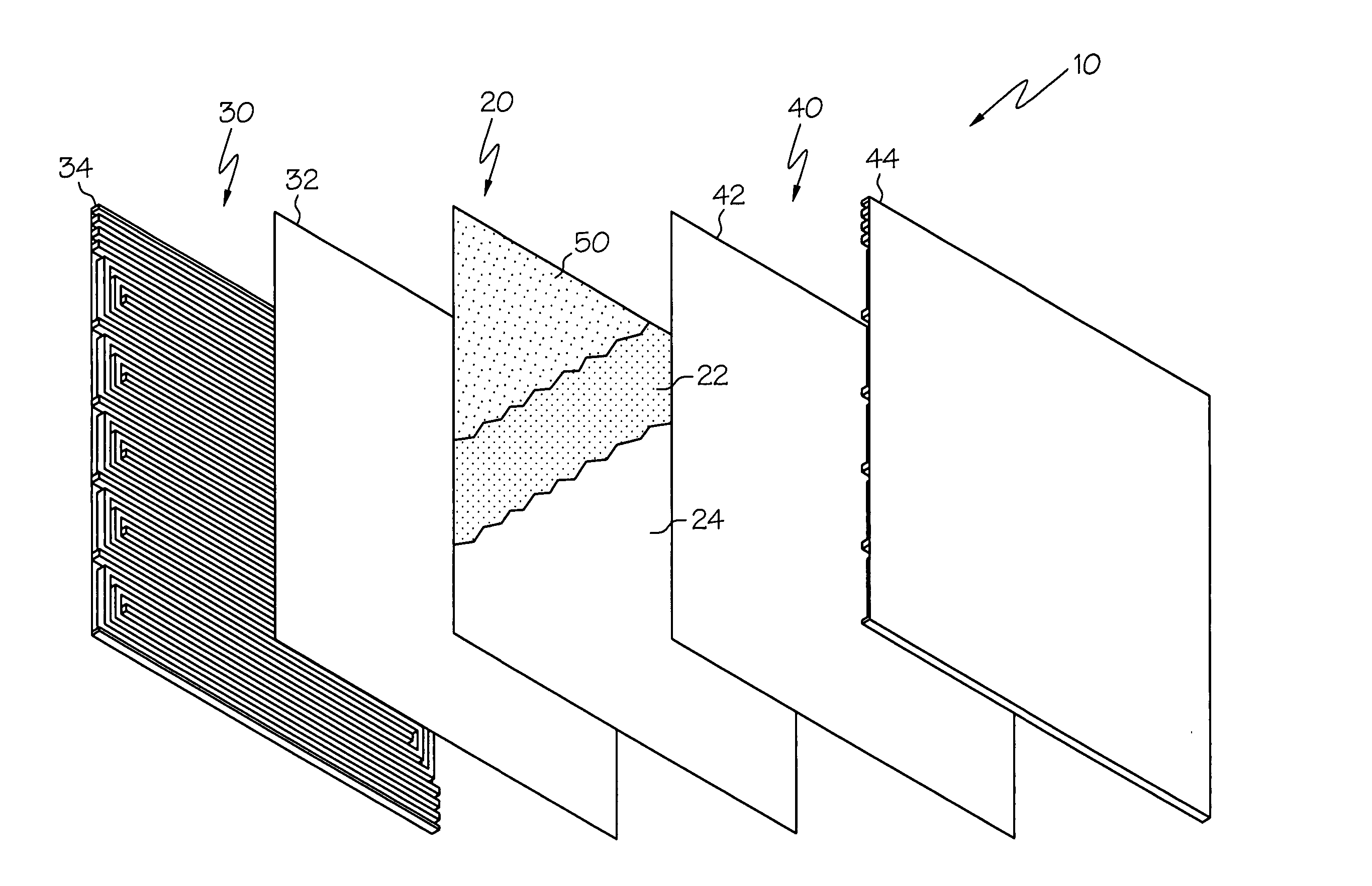
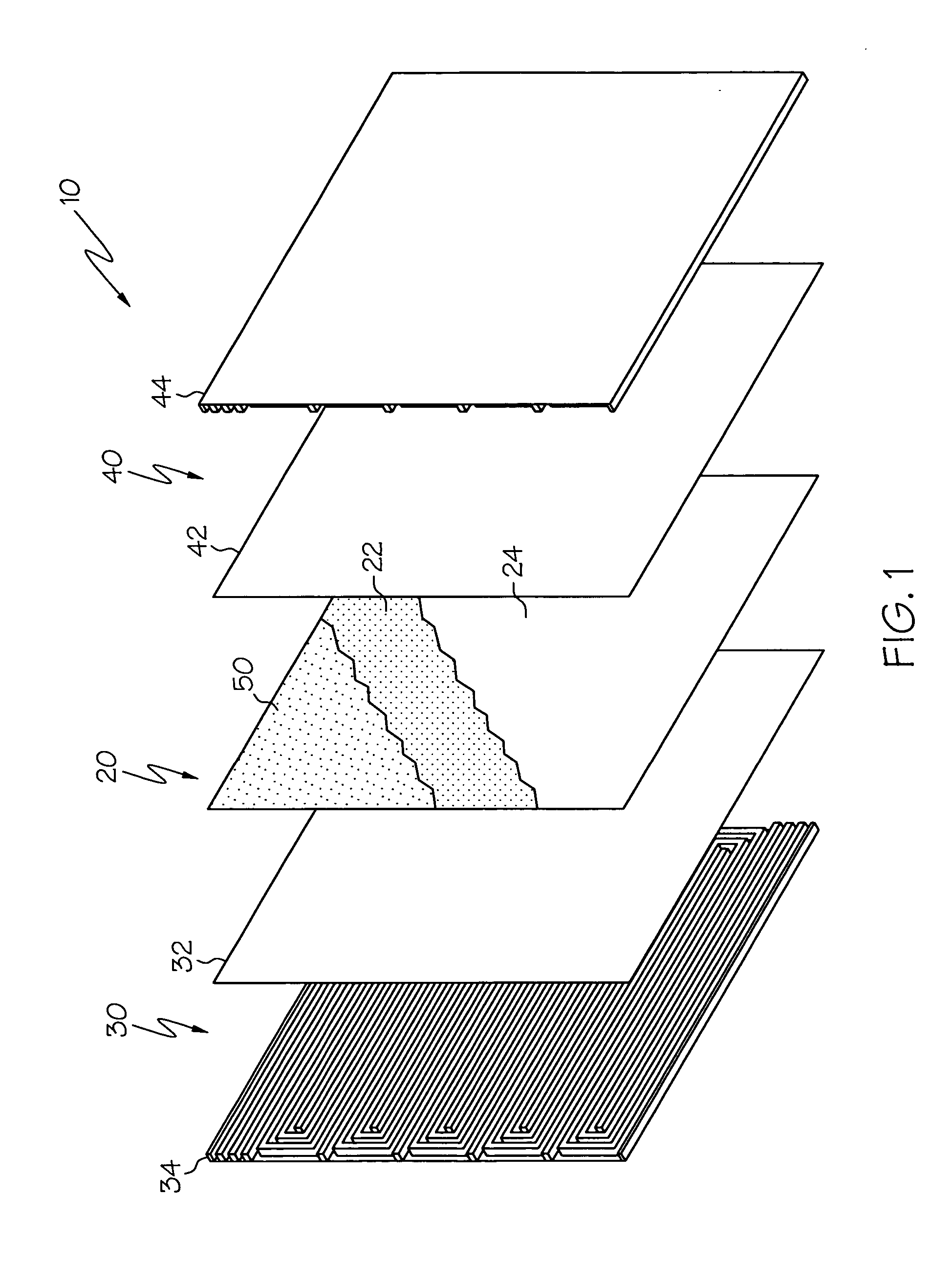
[0019] Referring to the exploded view of FIG. 1, noting that the general construction and operation of electrochemical conversion cells are beyond the scope of the present invention and may be gleaned from any suitable source covering electrochemical conversion cells, some typical components of an electrochemical conversion cell 10 are illustrated. Specifically, and not by way of limitation, an electrochemical conversion cell 10 according to the present invention is configured to convert first and second reactants R1, R2, to electrical energy. The illustrated cell 10 comprises a membrane electrode assembly 20 and first and second flowfield portions 30, 40 disposed on opposite sides of the membrane electrode assembly 20.

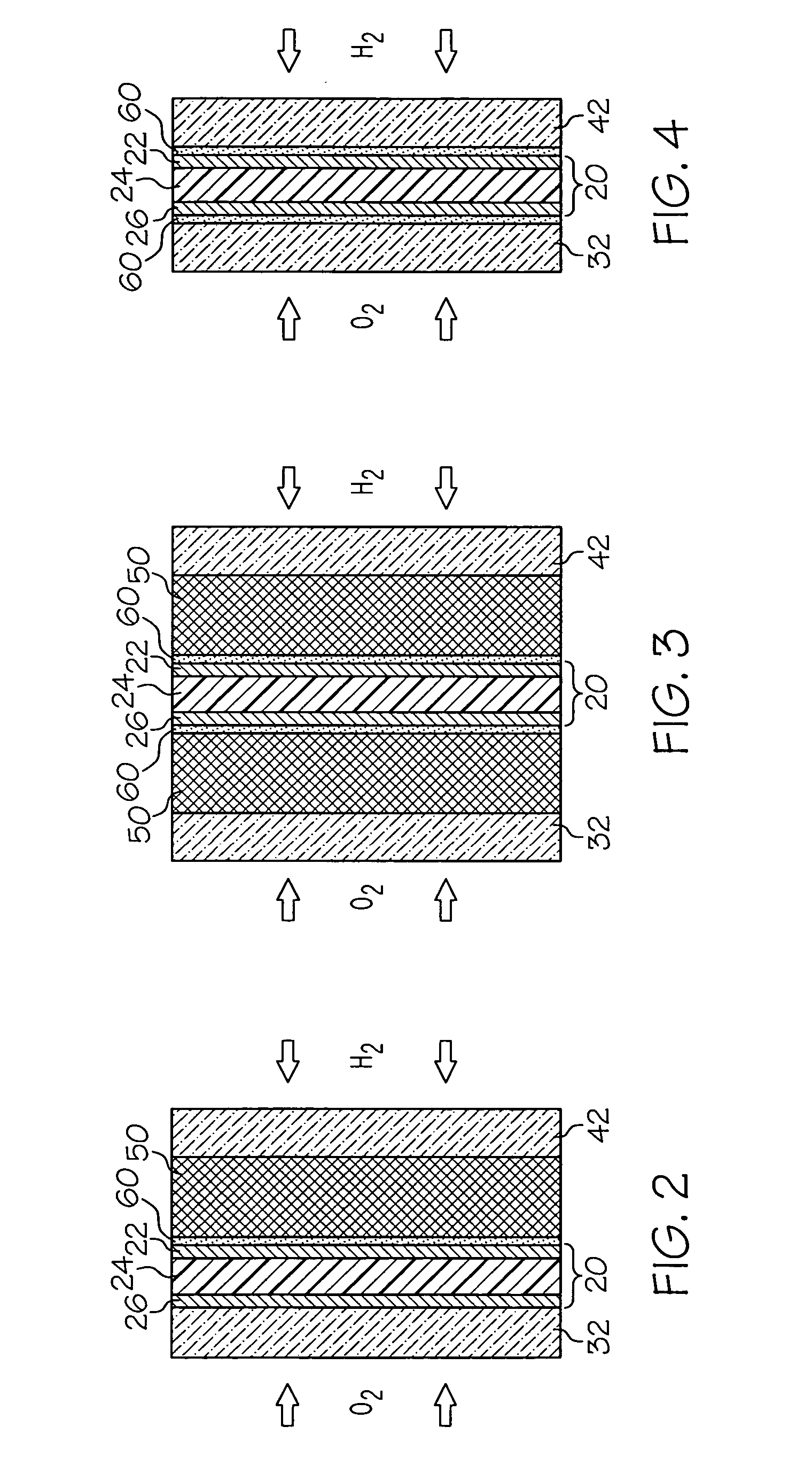
[0020] Referring to FIG. 2, although the present invention is not limited to a particular class of membrane electrode assemblies, for the purposes of illustration, it is noted that typical membrane electrode assemblies 20 comprises a catalytic anode 22 formed on a fi...


PUM

PropertyMeasurementUnit
electrical energyaaaaaaaaaa
degree of operational stressaaaaaaaaaa
stressaaaaaaaaaa

Abstract

The present invention is directed to addressing performance issues attributable to membrane electrode assemblies, and the components thereof, in electrochemical conversion cells. In accordance with one embodiment of the present invention, a device comprising at least one electrochemical conversion cell is provided. The cell is configured to convert first and second reactants to electrical energy and comprises a membrane electrode assembly and at least one membrane reinforcement layer. The combination of elastic modulus and thickness of the reinforcement layer and the bond between the reinforcement layer and the membrane electrode assembly are sufficient to enhance the structural integrity of the membrane electrode assembly beyond the operational degradation threshold of the assembly.

Description

BACKGROUND OF THE INVENTION [0001] The present invention relates to electrochemical conversion cells, commonly referred to as fuel cells, which produce electrical energy by processing first and second reactants, e.g., through oxidation and reduction of hydrogen and oxygen. By way of illustration and not limitation, a typical cell comprises a membrane electrode assembly positioned between a pair of gas diffusion media layers. A cathode flow field plate and an anode flow field plate are positioned on opposite sides of the cell unit, adjacent the gas diffusion media layers. The voltage provided by a single cell unit is typically too small for useful application. Accordingly, a plurality of cells are typically arranged and connected consecutively in a “stack” to increase the electrical output of the electrochemical conversion assembly or fuel cell. BRIEF SUMMARY OF THE INVENTION [0002] The present invention is directed to addressing performance issues attributable to membrane electrode ...

Claims


Application Information

Patent Timeline
Patent Type & Authority Applications(United States)
IPC IPC(8): H01M8/10H01M4/94
CPCH01M4/8605H01M4/8647H01M8/1004Y02E60/521Y02E60/50
Inventor LAI, YEH-HUNGMILLER, DANIELLITTEER, BRIAN A.GITTLEMAN, CRAIG S.BUDINSKI, MICHAEL K.
Owner GM GLOBAL TECH OPERATIONS LLC
Why Eureka
Try Eureka