Apparatus for performing biochemical processing using container having wells

a biochemical and container technology, applied in the direction of specific use bioreactors/fermenters, enzymology, after-treatment of biomass, etc., can solve the disadvantage of amplification and purification in a limited space, and achieve the effect of reducing processing time and downsizing the apparatus

Inactive Publication Date: 2007-04-05
CANON KK
View PDF7 Cites 93 Cited by
  • Summary
  • Abstract
  • Description
  • Claims
  • Application Information

AI Technical Summary

Benefits of technology

[0014] The present invention provides a biochemical processing apparatus including a structure including a heating section and a cooling section, and components of the structure are arranged so as to downsize the apparatus and reduce the processing time.

Problems solved by technology

Unfortunately, for amplification, the reaction section is subjected to a thermal cycle between about 55° C. and 95° C. If the reaction section is close to the cold storage section, the temperature of the thermal cycle may be conducted to the cold storage section.
Furthermore, purification after the amplification may be disadvantageously performed in a limited space.

Method used


Image

  • Apparatus for performing biochemical processing using container having wells
  • Apparatus for performing biochemical processing using container having wells
  • Apparatus for performing biochemical processing using container having wells

Examples


first embodiment

[0042] The amplifying section of a DNA testing apparatus according to an embodiment will now be described.

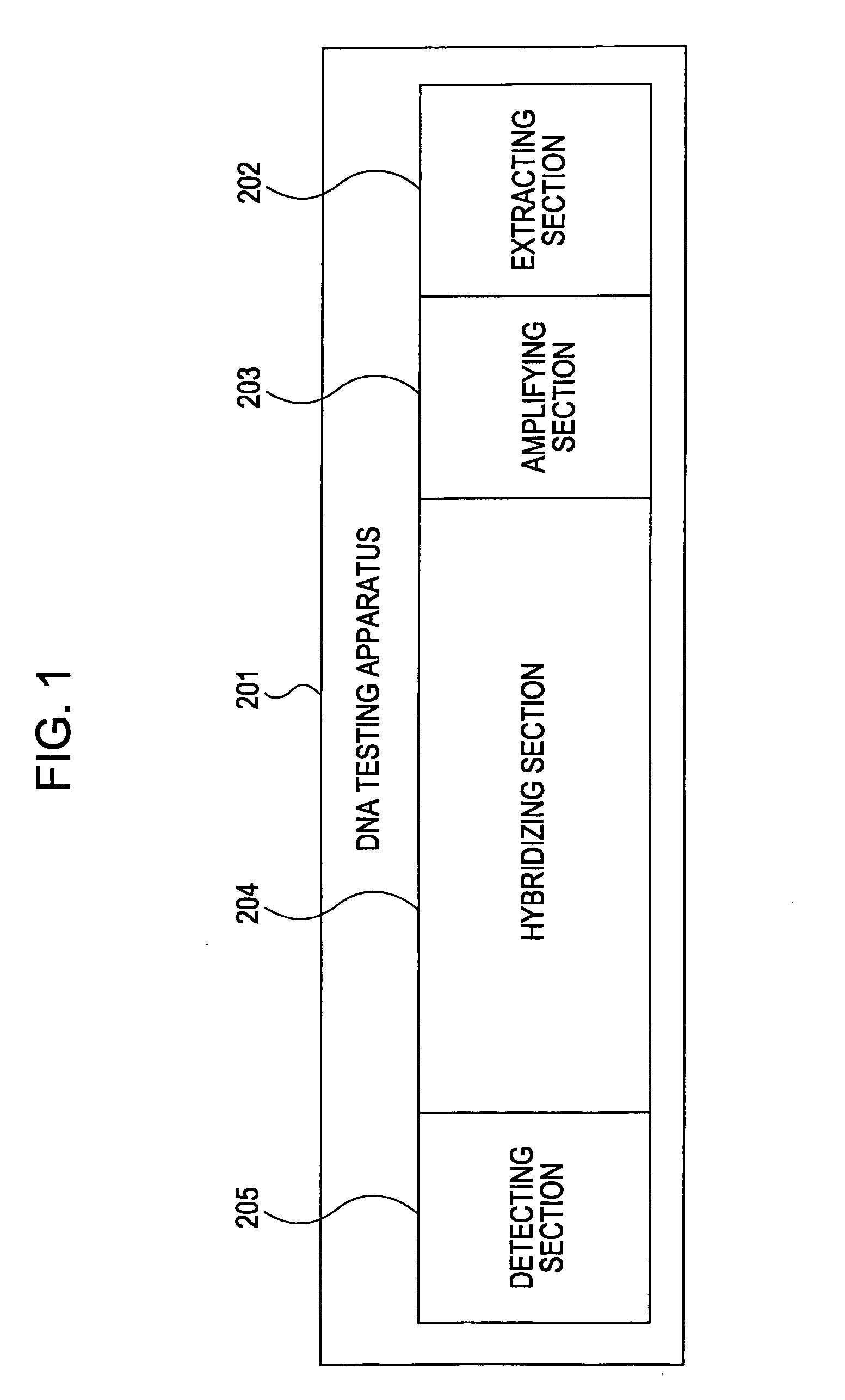
[0043]FIG. 1 is a schematic diagram of the DNA testing apparatus.

[0044] The DNA testing apparatus 201 includes an extracting section 202 for extracting DNA from a living body, amplifying section 203 for amplifying the DNA, a hybridizing section 204 for binding the amplified DNA to DNA probes, and a detecting section 205 for detecting whether the DNA is bound to the DNA probes. The test process proceeds through the extracting section, the amplifying section, the hybridizing section, and the detecting section in that order.

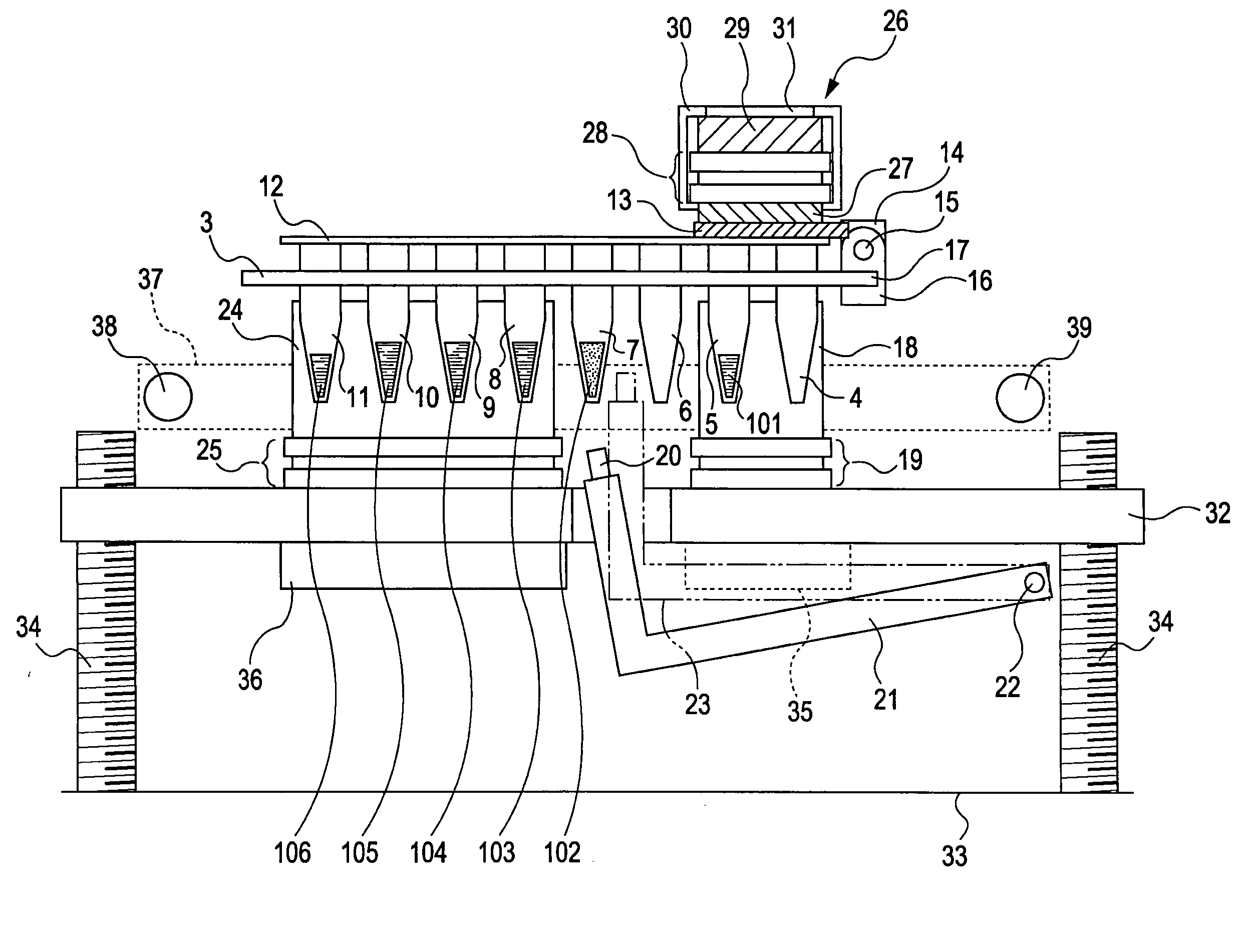
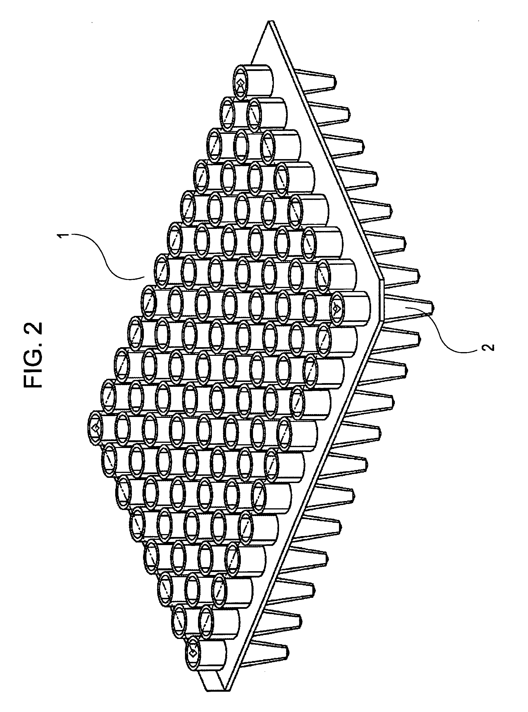
[0045]FIG. 2 is a perspective view of wells of a reaction / storage container.

[0046] A commercially available propylene PCR microplate 1 or its equivalent is used as the wells, and the wells are arrayed in an 8×12 matrix at a pitch of 9 mm. The bottom end 2 of each well has a shape that can be fitted with the below-described thermal cycle block and cooling blo...

second embodiment

[0108] Although the first embodiment uses a commercially available PCR microplate with wells arrayed at a pitch of 9 mm or its equivalent as the reaction / storage container, the reaction / storage container used in the present invention is not limited to this PCR microplate. The pitch of the wells, including recesses of the thermal cycle block and the cooling block, may be reduced or increased if necessary. The number of wells is not also limited to 96, and can be set according to the types of reagent and the number of analytes.

[0109] The wells may not be in a form of tapered cylinder, and may be in any form as long as the wells can come into tight contact with the thermal cycle block and the cooling block and purification can be performed.

third embodiment

[0110] Although the reaction / storage container 3 of the first embodiment contains only the reagents used for amplification, reagents used for other steps (of extraction, hybridization, and detection) may be contained.

[0111] In this instance, reagents that do not need temperature control or deteriorate by changes in temperature may be placed in wells between the cold storage section and the thermal cycle section.


PUM

PropertyMeasurementUnit
temperatureaaaaaaaaaa

Abstract

A biochemical processing apparatus includes a thermal cycle section, a processing section for performing a processing not requiring heating or cooling, and a cooling section. These sections are arranged in that order and opposed to a container with a plurality of wells.

Description

BACKGROUND OF THE INVENTION [0001] 1. Field of the Invention [0002] The present invention relates to biochemical processing apparatus for biochemically processing analytes, and particularly to a DNA testing apparatus including sections for amplifying and purifying DNA analytes. [0003] 2. Description of the Related Art [0004] In order to rapidly and accurately analyze nucleotide sequences or to detect a target nucleic acid in a nucleic acid sample, many approaches have been proposed which use hybridization reactions with probe carriers, such as DNA microarrays. The DNA microarray includes probes having nucleotide sequences that may be complementary to a target nucleic acid and the probes are closely fixed on a solid phase, such as beads or a glass plate. In general, the target nucleic acid is detected through the following steps. [0005] First, a target nucleic acid is extracted from a living body sample, such as blood or urine. [0006] In the second step, the extracted target nucleic ...

Claims


Application Information

Patent Timeline
Patent Type & Authority Applications(United States)
IPC IPC(8): C12M1/34
CPCB01L7/52B01L7/54B01L2200/10B01L2300/0829B01L2300/1822B01L2300/1827Y10S435/809
Inventor OKAMOTO, HIDEAKINUMAJIRI, YASUYUKI
Owner CANON KK
Why Eureka
Try Eureka