
Voltage regulating systems responsive to feed-forward information from deterministic loads

Inactive Publication Date: 2007-04-05
WESTERN DIGITAL TECH INC
View PDF21 Cites 20 Cited by
  • Summary
  • Abstract
  • Description
  • Claims
  • Application Information

AI Technical Summary

Benefits of technology

[0011] The present invention includes voltage regulating systems that adjust their output control signals in response to feed-forward information that is indicative of a deterministic change in the load current. A feed-forward circuit of the present invention provides a feed-forward signal in response to an input signal generated from a source that is external to the voltage regulating system. A voltage regulator system of the present invention can proactively respond to the feed-forward information, thereby improving the regulation tolerance to dynamic loading.

Problems solved by technology

However, when significant changes in the load current occur, the deviation in the output voltage can be large enough to exceed acceptable operating voltage limits, before the regulator responds and causes the output voltage to recover.
The downside of this solution for switching voltage regulators can be a loss of regulator efficiency, increased power dissipation, loss of noise margin, and less than optimal transient response.
The downside of multi-phase switching voltage regulators is that they can increase the cost and the electrical component count.
However, linear regulators are less efficient than switching voltage regulators and cause increased power dissipation.
These problems occur because a linear regulator operates the pass element in its linear region, and causes the pass element to be on all the time.
However, this method can cause a switching regulator to over-respond to a change in load current and to lose regulator stability.

Method used


Image

  • Voltage regulating systems responsive to feed-forward information from deterministic loads
  • Voltage regulating systems responsive to feed-forward information from deterministic loads
  • Voltage regulating systems responsive to feed-forward information from deterministic loads

Examples


first embodiment

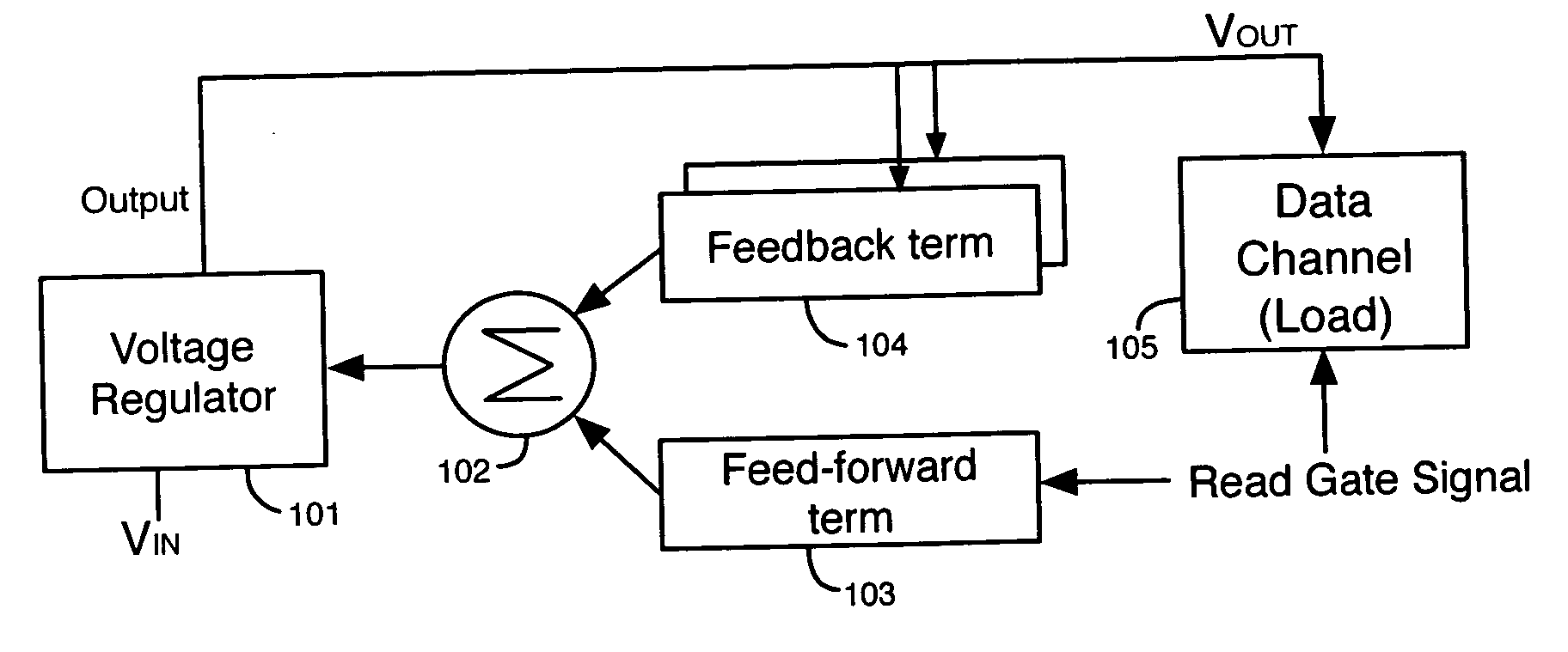
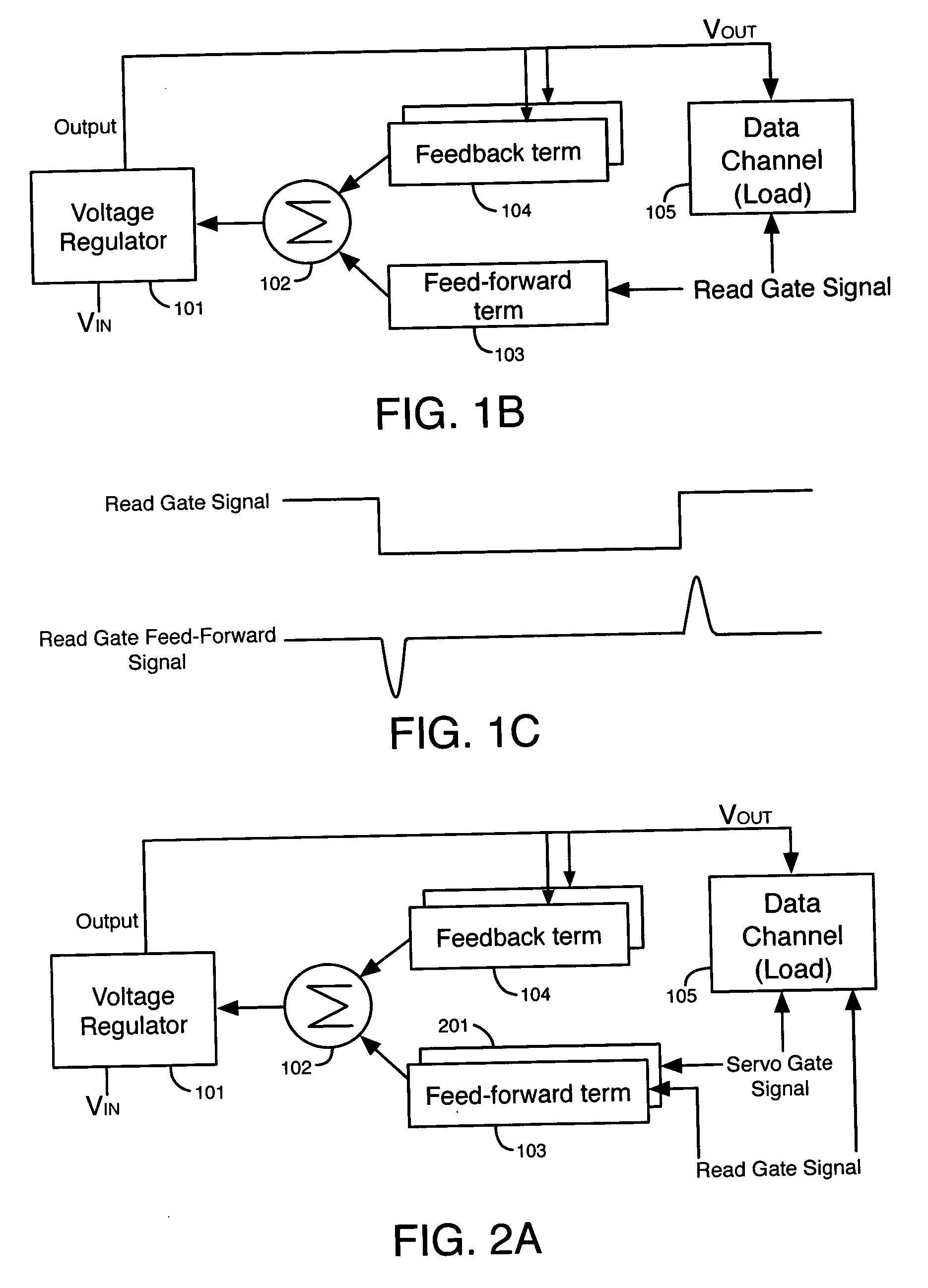
[0029]FIG. 1B illustrates a voltage regulating system 100 according to the present invention. Voltage regulating system 100 includes a voltage regulator 101, a summing node 102, a feed-forward term 103, and one or more feedback terms 104. Data channel 105 is the load in the hard disk drive that draws current from the output of the voltage regulator 101.

[0030] Voltage regulator 101 can be a synchronous switching voltage regulator, a non-synchronous switching voltage regulator, a linear voltage regulator, or any other type of voltage regulator. Voltage regulator 101 receives an input voltage VIN and provides an output voltage VOUT at its output to data channel 105. If voltage regulator 101 is a switching regulator, it typically includes an output inductor and an output capacitor for maintaining a continuous output voltage and / or current flow.

[0031] Each feedback term 104 receives a feedback signal from the output of voltage regulator 101. The feedback signal can be, for example, a vo...

second embodiment

[0042]FIG. 2A illustrates a voltage regulating system 200 according to the present invention. System 200 includes all of the elements of system 100 and an additional feed-forward term 201. Feed-forward term 201 receives a servo gate signal. A servo gate signal is a signal generated by a HDD controller to cause data channel 105 to read a servo track on a hard disk.

[0043] An example of a digital servo gate signal is illustrated in FIG. 2B. Feed-forward term 201 generates the servo gate feed-forward signal in response to the servo gate signal. Rising and falling pulses in the servo gate feed-forward signal correspond to rising and falling edges, respectively, of the digital servo gate signal. The feedback control signals, the read gate feed-forward signal, and the servo gate feed-forward signal from feed-forward term 201 are summed at node 102 and then provided to regulator 101.

[0044] In the example of FIG. 2B, data channel 105 increases its load current by a predictable amount in res...

third embodiment

[0046]FIG. 3 illustrates a voltage regulating system 300 that is responsive to feed-forward information indicative of deterministic changes in the load current, according to the present invention. Voltage regulating system 300 includes all of the elements of system 100, term selector register 301, variable weighting register 302, summing circuit 303, and hardware / software control unit 304. Voltage regulating system 300 is responsive to feed-forward signals indicative of several different deterministic events that affect the load current at load 105.

[0047] Control unit 304 can be a software-based or hardware-based system. Control unit 304 provides control signals that are indicative of deterministic changes in the load current drawn by load 105. For example, control unit 304 can provide a read gate signal, a servo gate signal, a write gate signal, etc. Control unit 304 stores the current states of these control signals in term selector register 301. For example, each storage unit in ...


PUM


Abstract

Voltage regulating systems are provided that adjust their output control signals in response to feed-forward information that is indicative of deterministic changes in the load current. A feed-forward circuit provides a feed-forward signal in response to an input signal generated from a source that is external to the voltage regulating system. The voltage regulator systems can proactively respond to the predictive information by adjusting their output, thereby improving the regulation tolerance to dynamic loading. As an example, the feed-forward information can include signals indicating multiple deterministic events that affect the load. Signals from multiple events can be summed together to generate a feed-forward term. As another example, the voltage regulating systems can be responsive to feedback information and feed-forward information from internal to the regulator, in addition to external deterministic information.

Description

BACKGROUND OF THE INVENTION [0001] 1. Field of the Invention [0002] The present invention relates to voltage regulating systems, and more particularly, to voltage regulating systems that are responsive to feed-forward information indicative of deterministic changes in the load current. [0003] 2. Description of the Related Art [0004] A voltage regulator is a circuit that provides a substantially constant output voltage to a load from an input voltage source. Switching voltage regulators and linear voltage regulators are two types of voltage regulators. In linear voltage regulators, a pass element (e.g., a transistor) is coupled in series between the input voltage source and the load. The linear voltage regulator controls the current through and / or voltage across the pass element to maintain a constant output voltage. Another possible feature of such a regulator may be to regulate the output current in addition to the output voltage. [0005] In a switching voltage regulator, a switch (...

Claims


Application Information

Patent Timeline
IPC IPC(8): G05D11/00G05D17/00G05D3/12G05D5/00G05D9/00
CPCH02M3/156H02M2001/0019H02M1/0019G05F1/10
Inventor DONALDSON, JAMES EDDYROWAN, BRYAN SCOTT
Owner WESTERN DIGITAL TECH INC
Learn More