System and method for controlling the rotating speed of a fan

a technology of rotating speed and fan, which is applied in the direction of motor/generator/converter stopper, dynamo-electric converter control, instruments, etc., can solve the problem of high manufacturing cos

Inactive Publication Date: 2007-04-12
HON HAI PRECISION IND CO LTD
View PDF7 Cites 19 Cited by
  • Summary
  • Abstract
  • Description
  • Claims
  • Application Information

AI Technical Summary

Benefits of technology

[0005] A system for controlling the rotating speed of a fan is provided in accordance with a preferred embodiment. The system typically includes a system ambient thermal spot, a fan speed controller, a temperature reading module, a comparison module and a processing module. The temperature reading module is used for reading a standard temperature value of a central processing unit (CPU), a temperature value of a thermal diode of the CPU, and a temperature value of the system ambient thermal spot. The comparison module is used for comparing the temperature value of the thermal diode with a minimum temperature value at which the fan begins to process the heat of the CPU, comparing the temperature value of the system ambient thermal spot with a critical temperature value if the temperature value of the thermal diode is not larger than the minimum temperature value, and obtaining comparison results. The processing module is used for setting pulse-width modulation (PWM) duty cycles of the fan according to the comparison results, and sending the duty cycles to the fan speed controller for controlling the rotating speed of the fan.

Problems solved by technology

The conventional mechanical type and electronic type fan speed control devices are commonly complicated, resulting in a high manufacturing cost.

Method used


Image

  • System and method for controlling the rotating speed of a fan
  • System and method for controlling the rotating speed of a fan
  • System and method for controlling the rotating speed of a fan

Examples


Embodiment Construction

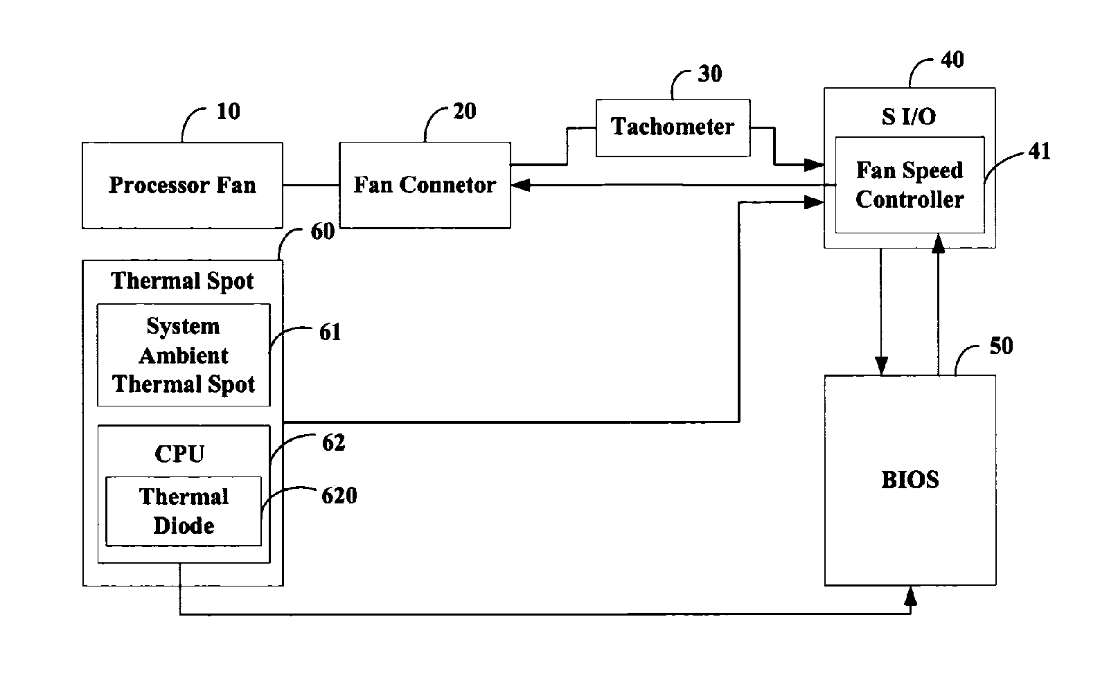
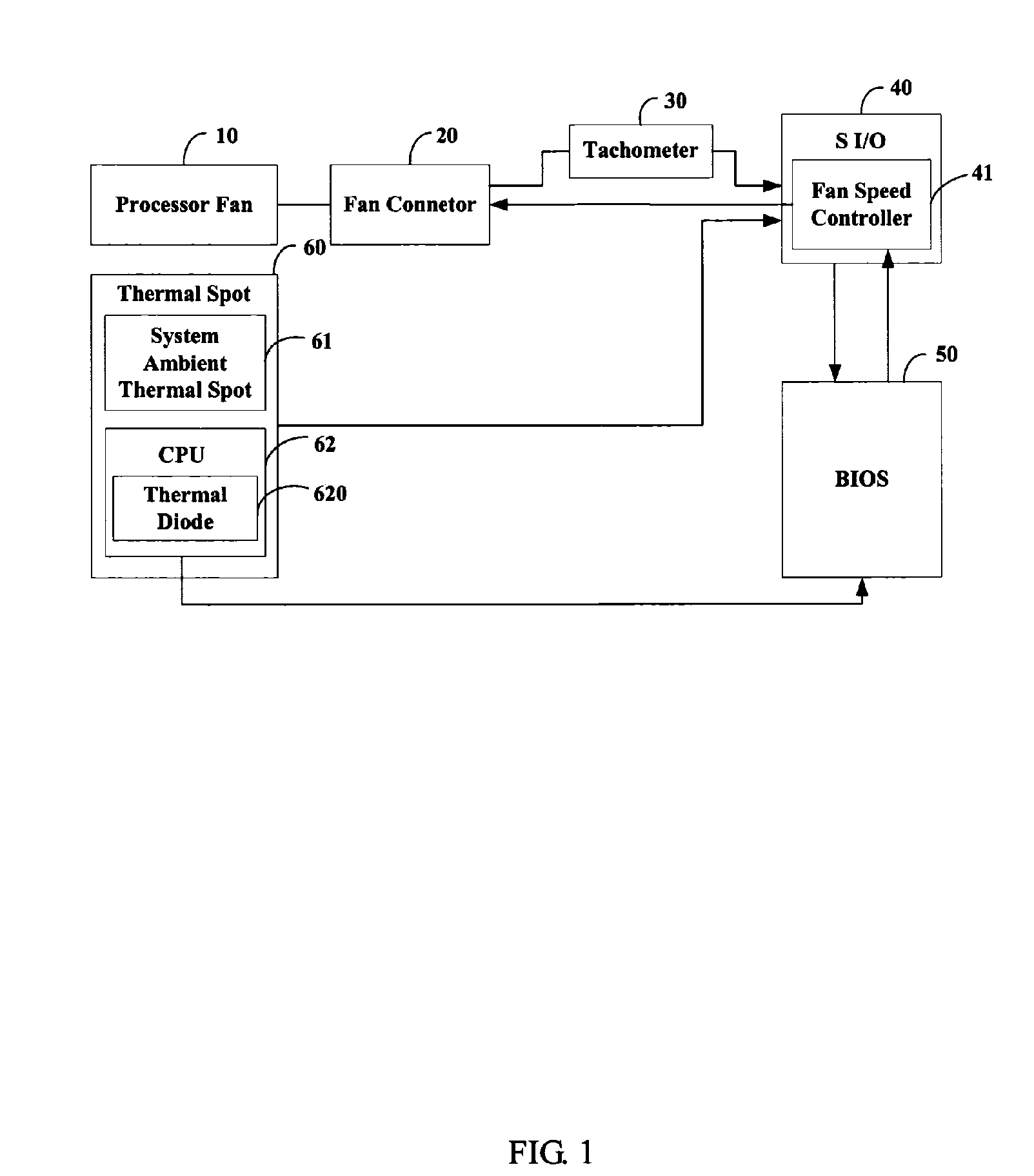
[0012]FIG. 1 is a hardware configuration schematic diagram of a system for controlling the rotating speed of a fan in accordance with one preferred embodiment. In the preferred embodiment, the system mainly includes: a fan 10 that is typically configured on a balanced technology extended (BTX) motherboard of a computer system, a fan connector 20, a tachometer 30, a super input / output (S I / O) 40, a basic input output system (BIOS) 50 and a thermal spot 60. The fan 10 may be a pulse-width modulation (PWM) fan. The fan connector 20 may be a four-pin fan connector or a five-pin fan connector. The tachometer 30 is connected with the fan 10 via the fan connector 20, and is used for recording the rotating speed of the fan 10. The S I / O 40 is used for sensing a temperature of the thermal spot 60, and converting the temperature into a temperature value Td. The thermal spot 60 includes a system ambient thermal spot 61 and a central processing unit (CPU) 62. The system ambient thermal spot 61 ...


PUM


Abstract

A method for controlling the rotating speed of a fan is disclosed. The method includes the steps of: reading a standard temperature Tc of a central processing unit (CPU); reading a thermal diode's temperature Td and a system ambient temperature Ta; comparing Td with a minimum temperature Tl, such that the fan begins processing the heat of the CPU begins; if Td>Tl, increasing pulse-width modulation (PWM) duty cycle of the fan to 100%; if Td<=Tl, comparing a critical temperature T0 with Ta; if Ta>T0, increasing PWM fan duty cycle to 100%; if Ta<=T0, setting the fan duty cycle at 40%; sending the PWM fan duty cycle to a fan speed controller.

Description

FIELD OF THE INVENTION [0001] The present invention is generally related to a system and method for controlling the rotating speed of a fan. DESCRIPTION OF RELATED ART [0002] It is known that a central processing unit (CPU) of a computer generates heat while operating. The higher the operating speed of the CPU is, the higher the temperature is. A cooling device such as a fan is adopted to lower the temperature. When the temperature around the CPU is too high, the fan immediately starts rotating at a predetermined speed. When the temperature around the CPU is relatively low, the fan is stopped in order to save power. A fan speed control device, which has two types, namely, a mechanical type and an electronic type, controls the rotating speed of the fan. [0003] Conventional mechanical type speed control devices commonly use a press-button switch or a rotary switch to control shift contacts of the fan motor. A user has to press the press-button switch or rotate the rotary switch to a d...

Claims


Application Information

Patent Timeline
IPC IPC(8): H02P7/29
CPCG06F1/206
Inventor HSIANG, SUNG-JENCHANG, YUH-CHINGLO, CHIEN-YILEE, PUH-YUN
Owner HON HAI PRECISION IND CO LTD
Why Eureka
Try Eureka