
Intramedullary bone plate with sheath

a bone plate and intramedullary technology, applied in the field of implants and surgical devices, can solve the problems of increased potential for tendonitis and/or tendon rupture, insufficient span of medial lateral width to adequately span and immobilize fracture sites, and prior art has not been designed to stabilize comminuted fractures of the distal radius. , to achieve the effect of enhancing bone fixation and rotational stability

Inactive Publication Date: 2007-04-12
TORNIER INC
View PDF80 Cites 74 Cited by
  • Summary
  • Abstract
  • Description
  • Claims
  • Application Information

AI Technical Summary

Benefits of technology

[0004] The present invention provides an intramedullary bone plate with sheath having an intramedullary stem element that is composed of a proximal portion and a distal portion. The exterior surface of the distal portion being configured, for example shaped or dimensioned by machined means, surface treatments or applied three-dimensional surface coatings to enhance bone fixation and rotational stability. The proximal portion being of a smaller circular diameter and having an arced geometry in the sagittal plane, allowing for intramedullary contact and securement.

Problems solved by technology

A shortcoming and surgical complication caused by the prior art and the corresponding dorsal approach is an increased potential for tendonitis and / or tendon rupture caused by the device thickness and non-uniformity of the adjacent device surface.
The prior art also has not been designed to stabilize comminuted fractures of the distal radius in that these devices medial-lateral width is too narrow to adequately span and immobilize fracture sites.
Further, the prior arts' use of fixation pegs with set angle orientations does not allow for adequate bone fragment fixation in distal radius fractures.
The shortcoming of the volar approach is the presence of significant soft tissue and vascular anatomy and the resulting technically challenging implantation procedure of the surgical device.

Method used


Image

  • Intramedullary bone plate with sheath
  • Intramedullary bone plate with sheath
  • Intramedullary bone plate with sheath

Examples


Embodiment Construction

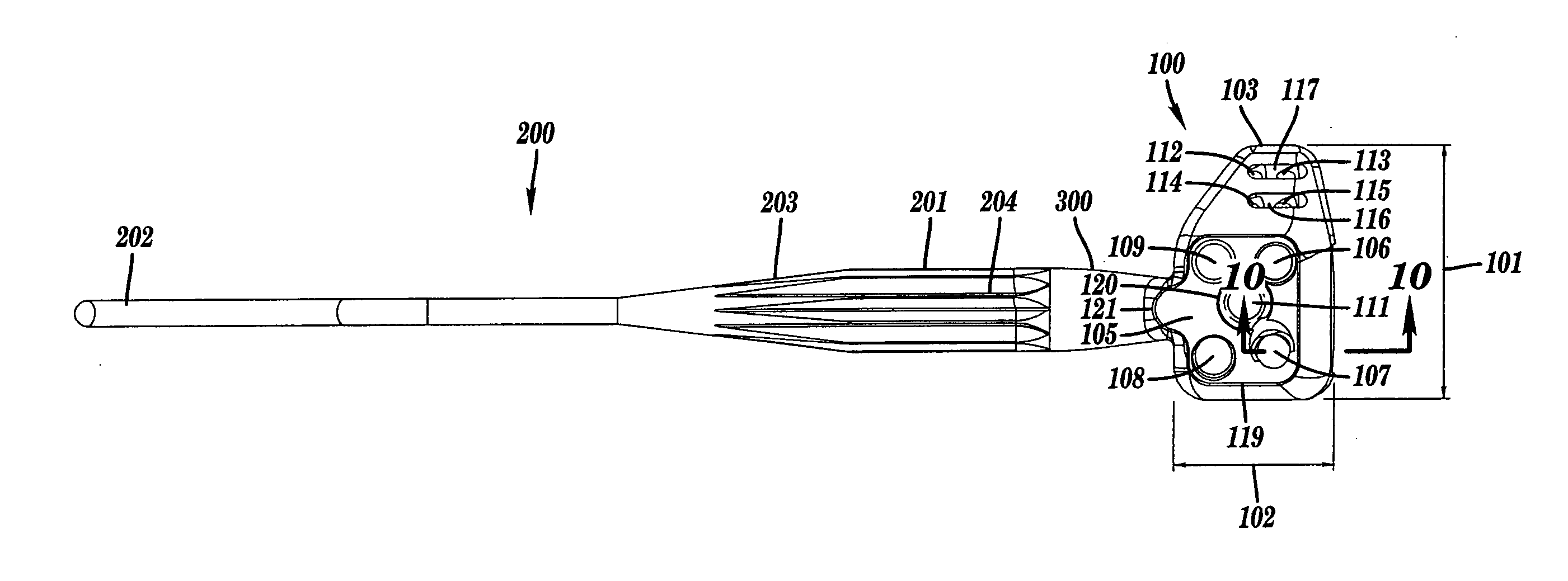
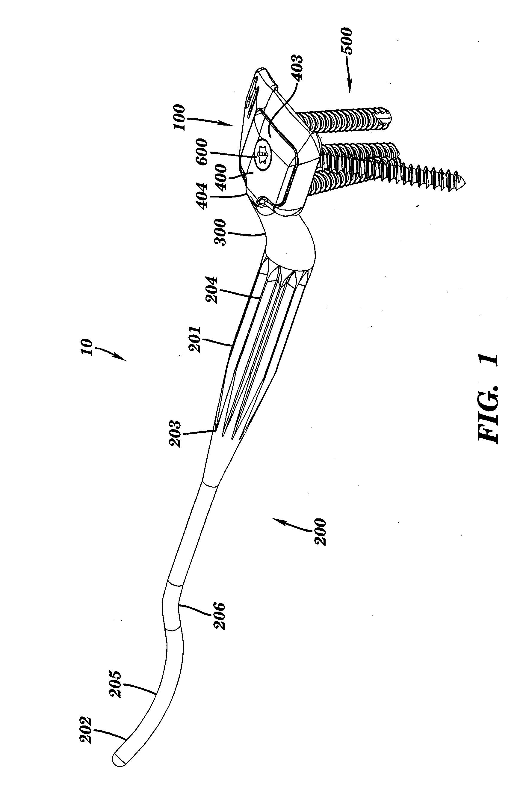
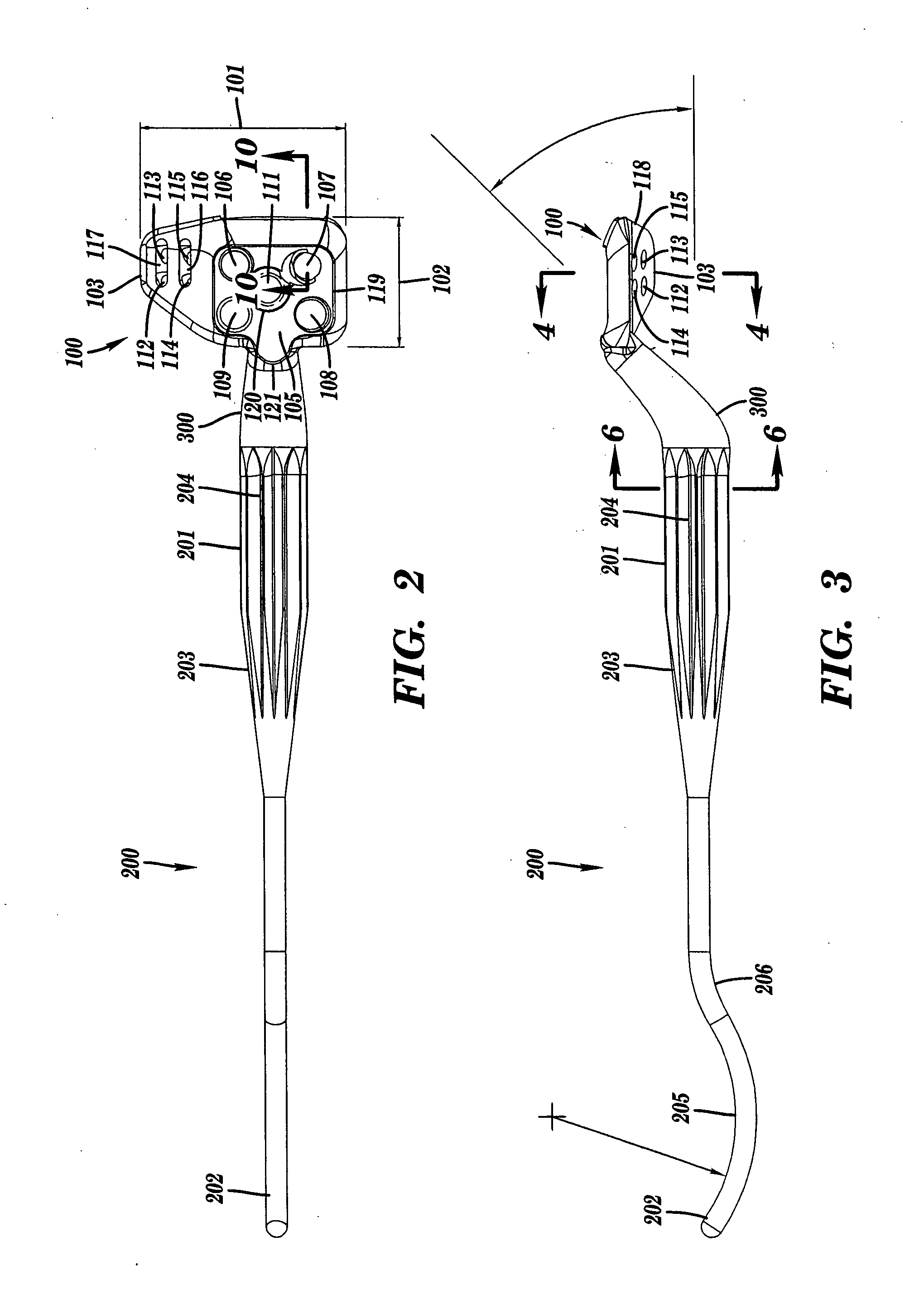
[0033]FIG. 1 shows the general arrangement of a preferred embodiment of the intramedullary bone plate with sheath 10 of this invention. Generally, the intramedullary bone plate with sheath 10 includes a bone plate head 100, an intramedullary stem 200, a connecting neck 300, a sheath 400, a bone screw 500, a sheath screw 600 and surgical k-wire (not shown). The various embodiments of the present invention, as described in greater detail below, result in the intramedullary bone plate with sheath designed to allow for greater intraoperative flexibility and fracture stabilization.

[0034] With reference to FIG. 2, the bone plate head 100 is shaped with the overall head width 101 being, preferably, greater than or equal to one half that of the longitudinal length of the head 102. As shown in FIG. 4, the medial tab member 103 is directed downward at an angle of approximately seventy degrees relative to the transverse plane, allowing for increased bone fragment capture. A sheath recess 105 ...


PUM


Abstract

An intramedullary bone plate with sheath having an intramedullary stem, a bone plate head and a neck that connects the intramedullary stem to the bone plate head in a manner where the stem and head are offset from each other longitudinally and axially in the sagittal plane. The bone plate head includes a sheath recess wherein non-threaded bone screw holes and a threaded sheath screw hole are located. Bone screws are inserted through the sheath recess and oriented at set angles allowing for bone fragment fixation and fracture reduction. A sheath element is placed within the boundaries of the sheath recess and secured with the sheath screw. The intramedullary stem includes longitudinal flutes in its distal portion and a bi-arced geometry in its proximal portion providing for stabilization of the implanted device. The bone plate head configuration provides for more complete fracture capture and multiple fixation modalities.

Description

FIELD OF THE INVENTION [0001] This invention relates generally to implantable, surgical devices and the method for implantation and, in particular, to an improved surgical device to be used in the internal fixation of fractures to the distal radius and other long bones. BACKGROUND OF INVENTION [0002] There are a variety of surgical devices and methods that are being used to treat fractures of the distal radius. Historically, open reduction and internal fixation (ORIF) of distal radius fractures has been accomplished by the implantation of various types of metallic plates, pegs, wires and screws utilizing a dorsal approach and securing such plates on the dorsal aspect of the radius. Examples of such devices can be found in U.S. Pat. Nos. 6,706,046 and 6,730,090. Implanting surgical devices using a dorsal approach is technically easier as critical vascular and soft tissue structures are avoided. A shortcoming and surgical complication caused by the prior art and the corresponding dors...

Claims


Application Information

Patent Timeline
IPC IPC(8): A61F2/30
CPCA61B17/72A61B17/7233A61B17/8042A61B17/8061
Inventor ELI RUNNING, DONALDONDRLA, JEFFREY MICHAELHUNT, THOMAS R. IIICHURCHILL, R. SEAN
Owner TORNIER INC
Learn More