Stent delivery system using a steerable guide wire

a technology of stent delivery and guide wire, which is applied in the field of stent delivery system using a steerable guide wire, can solve the problems of fixed guide wire, inability to steer, and inability to perform the same procedure, so as to save the cost of such a guide wire, reduce the time to perform the stent delivery procedure, and facilitate the stent delivery.

Active Publication Date: 2007-04-12
CARDINAL HEALTH SWITZERLAND 515 GMBH
View PDF37 Cites 25 Cited by
  • Summary
  • Abstract
  • Description
  • Claims
  • Application Information

AI Technical Summary

Benefits of technology

[0007] Another advantage of the present invention is that a separate guide wire is eliminated thus saving the cost of such a guide wire. Additionally, the time to perform a stent delivery procedure is reduced because a separate guide wire does not have to be placed prior to using the stent delivery system to place the stent at the site of a stenosis.
[0008] The present invention uses a steerable guide wire that extends for the entire length of the stent delivery system. A distal portion of the steerable guide wire can have its shaped changed after it is placed in the patient's vascular system by manipulation of the proximal portion of the steerable guide wire. Thus the shape of the guide wire's distal portion can be straight or highly curved or any curvature in between. This is a great advantage for getting the distal end of the steerable guide wire into the vessel that is to be stented more efficiently as compared to the use of a conventional guide wire.
[0009] An important feature of the present invention is a thin-walled, guide wire tube that extends for essentially the entire length of the balloon angioplasty catheter. The guide wire tube is fixedly and sealably attached at its proximal end and its distal end to the balloon angioplasty catheter. Specifically, the guide wire tube forms a liquid tight seal at its proximal end with the proximal fitting of the balloon angioplasty catheter and also a liquid tight seal at its distal end with the balloon onto which the stent is mounted.
[0010] Another important aspect of the present invention is the distal seal that is attached to the cylindrical distal end of the balloon and also the distal end of the guide wire tube. This seal is lubricity coated and also has a taper at a small angle in the distal direction that acts like a wedge to open a tight stenosis (sometimes called “Dottering”) in an artery. The outer diameter of the distal seal and the cylindrical distal section of the balloon are optimally equal to or slightly larger than the outer diameter of the stent as it is crimped onto the balloon prior to deployment of the stent. This diameter of the cylindrical distal section of the balloon and the distal seal, and the lubricity coating of the conical front surface of the distal seal, together provide the least resistance for pushing through a tight stenosis. Also, the pushability of the combined steerable guide wire and balloon angioplasty catheter work together to get the stent to be pushed through a tight stenosis.
[0011] It is envisioned that the guide wire tube would be fixedly attached to the guide wire at one or more locations. The attachment could be by either the use of an adhesive and / or by shrinking the guide wire tube down onto the outer surface of the guide wire to minimize the diameter of the stent delivery system.
[0012] It is also envisioned that instead of using a thin-walled guide wire tube to form a sealed inner liner for the inflation lumen of the balloon angioplasty catheter, the guide wire itself could be coated with a polymer to form a water tight seal. The polymer coating would then be sealed to the balloon angioplasty catheter at its proximal and distal ends. This embodiment while more difficult to produce would have a potentially smaller diameter than the embodiment using a separate tube shrunk down onto the guide wire's outer surface.

Problems solved by technology

Placing the guide wire requires additional procedure time and additional cost for the procedure.
This fixed, not steerable, guide wire system will not be as capable for rapid delivery of the stent through the tortuous coronary arteries as stent delivery systems that are advanced over a steerable guide wire.

Method used


Image

  • Stent delivery system using a steerable guide wire
  • Stent delivery system using a steerable guide wire
  • Stent delivery system using a steerable guide wire

Examples


Embodiment Construction

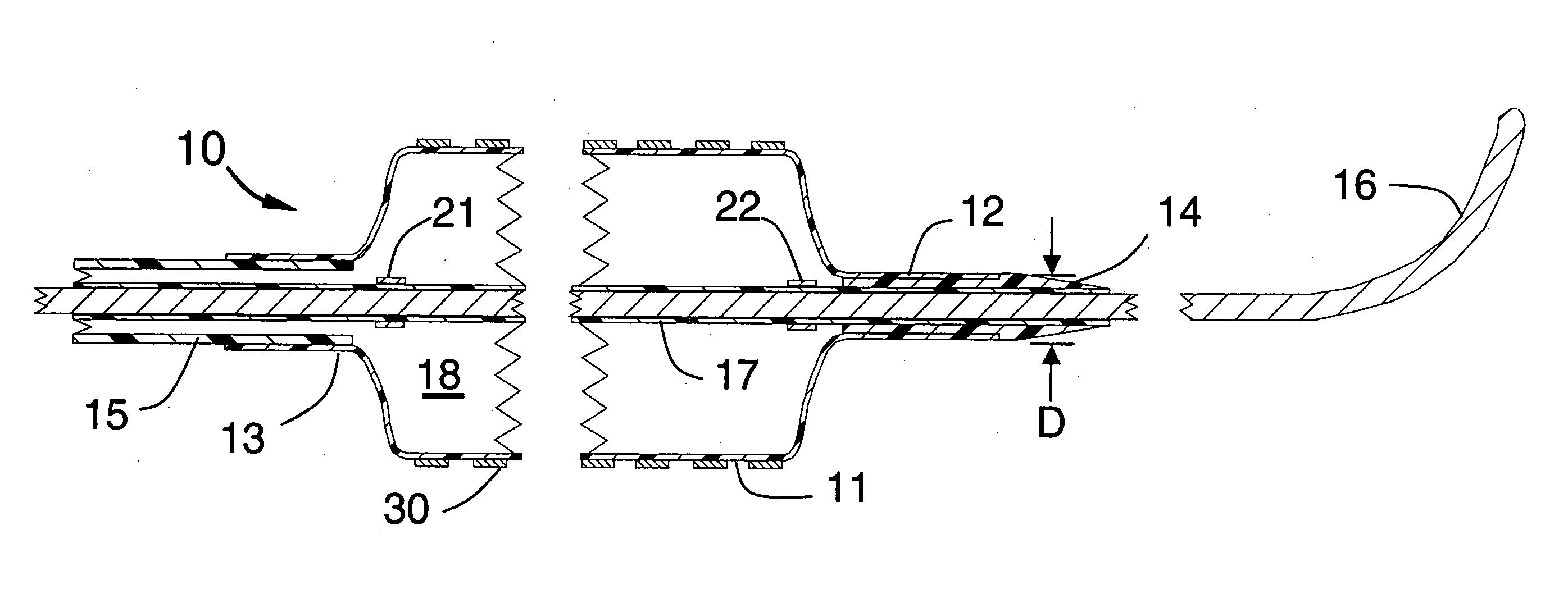
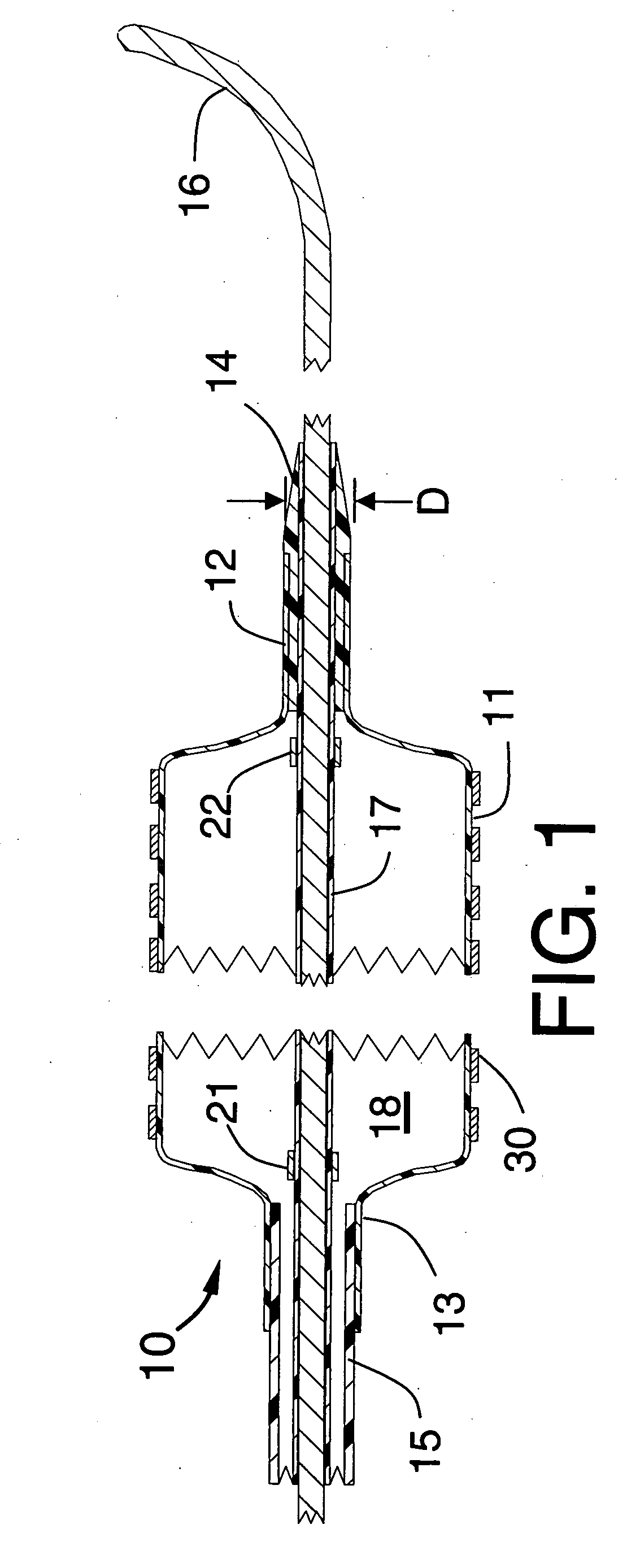
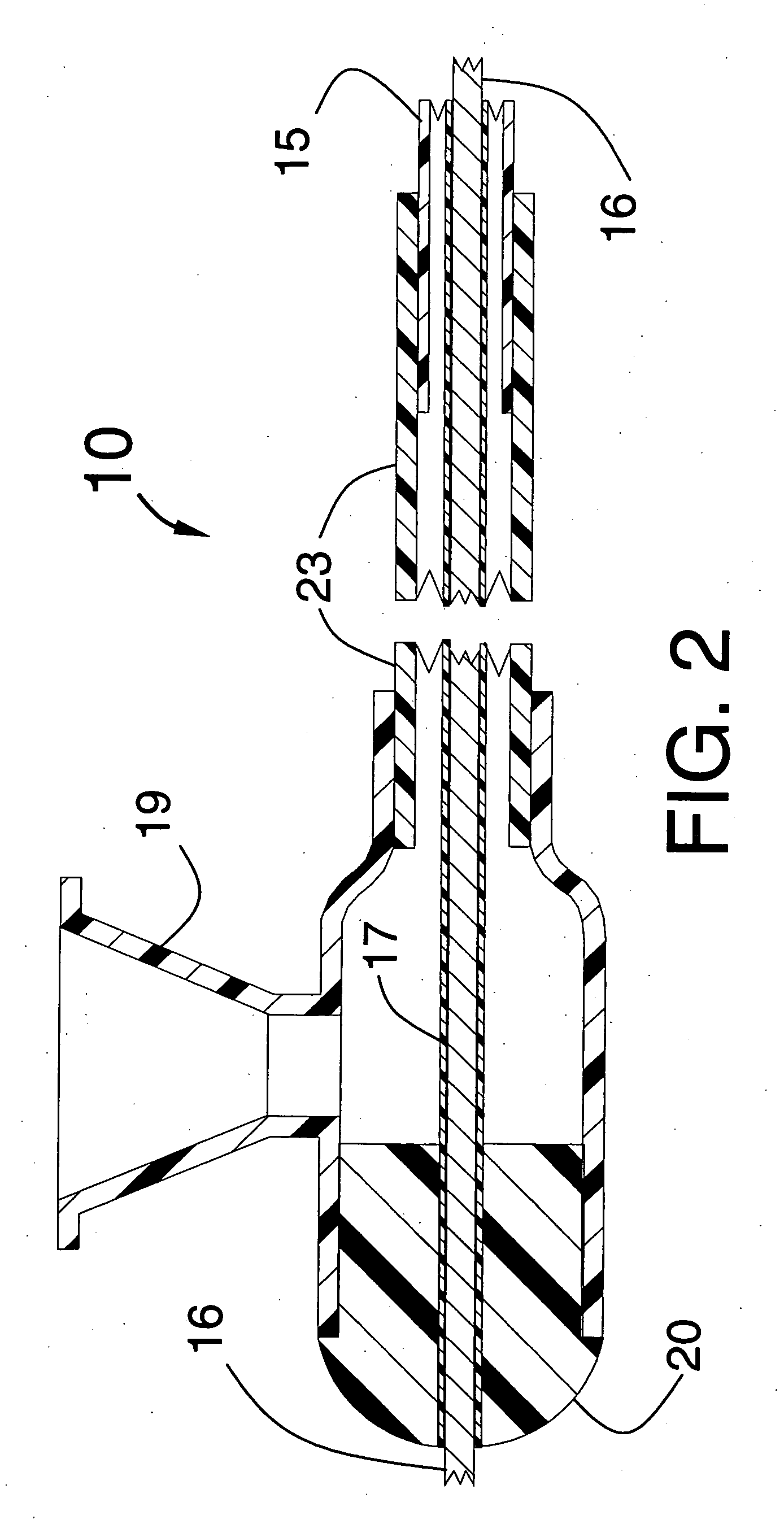
[0019]FIGS. 1, 2 and 3 illustrate a stent delivery system 10 having a fixed but steerable guide wire 16 that is placed within a guide wire tube 17. The distal end and proximal end of the guide wire tube 17 can be joined by a small amount of adhesive to fixedly attach the guide wire tube 17 to the steerable guide wire 16 to prevent the guide wire from moving longitudinally within the stent delivery system 10. The guide wire 16 would typically have a diameter that lies between 0.010 and 0.038 inches. The optimum diameter for use in coronary arteries will be approximately 0.014 inches.

[0020]FIG. 1 is a longitudinal cross section of a proximal portion of the stent delivery system 10 showing an inflated balloon 11 onto which the stent 30 is mounted, the balloon having a cylindrical distal section 12 that is fixedly attached to the distal seal 14 and the balloon 11 also having a cylindrical proximal section 13 that is fixedly attached to the distal end of the distal shaft 15. The distal ...


PUM


Abstract

A thin-walled guide wire tube is fixedly and sealably attached to both a proximal section and a distal section of a balloon angioplasty catheter. A stent is co-axially mounted onto the inflatable balloon of the balloon angioplasty catheter. Because the guide wire tube forms an inner liner for the balloon angioplasty catheter, the fluid inflation lumen of the catheter is sealed so the inflation liquid that pressurizes the balloon will not leak as it would be if there were no “inner liner” and the balloon angioplasty catheter were attached to the guide wire itself. By not having a traditional inner shaft through which a conventional guide wire slides, the deflated balloon on which the stent is mounted can have a reduced diameter.

Description

FIELD OF USE [0001] This invention is in the field of devices for percutaneous insertion into a vessel of the human body to place a stent at the site of an obstruction. BACKGROUND OF THE INVENTION [0002] Stents are well known devices for placement in vessels of the human body to obtain and maintain patency of that vessel. The greatest use for stents has been for placement within a stenosis in a coronary artery. When a stent is used for treating a coronary artery stenosis, it has always been necessary to first place a guide wire through the stenosis. The next step in the stenting procedure is typically to pre-dilate the stenosis with a balloon angioplasty catheter that is advanced over that guide wire. The balloon angioplasty catheter is then removed and a stent delivery system that includes the stent is advanced over the guide wire and the stent is then deployed at the site of the dilated stenosis. [0003] Recent improvements in the design of stent delivery systems have made it possi...

Claims


Application Information

Patent Timeline
Patent Type & Authority Applications(United States)
IPC IPC(8): A61F2/06
CPCA61F2/958A61F2/95A61M25/104A61M2025/1056A61M2025/1063
Inventor FISCHELL, DAVID R.FISCHELL, ROBERT E.FISCHELL, TIM A.FISCHELL, SCOTT J.S.
Owner CARDINAL HEALTH SWITZERLAND 515 GMBH
Why Eureka
Try Eureka