Method of estimating joint moment of bipedal walking body

a bipedal walking and joint moment technology, applied in the direction of instruments, applications, person identification, etc., can solve the problems of inconvenient increase of errors, deterioration of accuracy of estimating joint moment in the bending/stretching direction of legs, and difficulty in grasping every component of the three-dimensional displacement amount of joints with sufficient accuracy, so as to enhance the accuracy of estimating the vertical position of the acting point of the floor reaction force.

Inactive Publication Date: 2007-04-19
HONDA MOTOR CO LTD
View PDF3 Cites 22 Cited by
  • Summary
  • Abstract
  • Description
  • Claims
  • Application Information

AI Technical Summary

Benefits of technology

[0033] With this arrangement, in a state wherein only the portion adjacent to the toe side of the foot portion of the leg in contact with the ground is in contact with the ground, the position vertically away downward from the vertical position of the ankle joint of the leg by the vertical distance between the ankle joint and the metatarsophalangeal joint is estimated as the vertical position of the acting point of a floor reaction force. As a result, the accuracy of estimating the vertical position of the acting point of the floor reaction force can be enhanced.

Problems solved by technology

Therefore, there are many cases where bending motions of the legs are not performed on the sagittal plane of a vertical posture when a human being moves.
In such cases, there has been likelihood that the accuracy of estimating joint moments in the bending / stretching directions of the legs deteriorates in an embodiment of Patent Document 1 mentioned above.
For this reason, it is usually difficult to grasp every component of the three-dimensional displacement amounts of the joints with sufficiently high accuracy.
Hence, even if an attempt is made to estimate a joint moment in the bending / stretching directions of a leg by simply using a three-dimensional technique, there has been a danger in that an error inconveniently increases or an estimated value thereof inconveniently tends to suddenly changes (the robust performance deteriorates).

Method used


Image

  • Method of estimating joint moment of bipedal walking body
  • Method of estimating joint moment of bipedal walking body
  • Method of estimating joint moment of bipedal walking body

Examples


Embodiment Construction

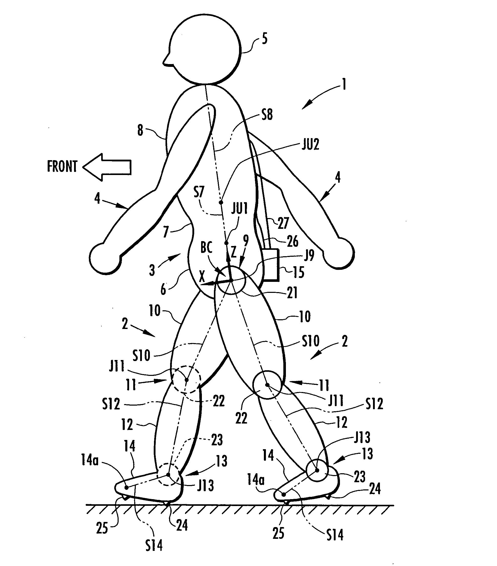
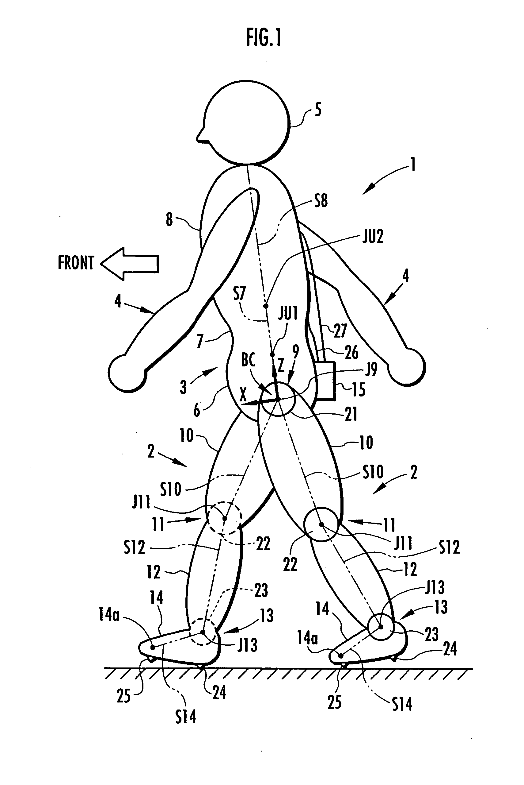
[0053] An embodiment of the present invention will be explained with reference to FIG. 1 to FIG. 14. FIG. 1 is a diagram schematically showing an overall apparatus construction in an embodiment in which the present invention has been applied to a human being as a bipedal walking body. As shown in the figure, the construction of a human being 1 is roughly divided into a pair of right and left legs 2, 2, a body 3, a pair of right and left arms 4, 4, and a head 5. The body 3 is constructed of a waist 6, an abdomen 7, and a chest 8, and the waist 6 is connected to the legs 2 and 2, respectively, through the intermediary of a pair of right and left hip joints 9, 9. Further, the arms 4 and 4 extend from both right and left sides of the chest 8 of the body 3, and the head 5 is supported on the top end of the chest 8. Each leg 2 is provided with a thigh 10 extending from a hip joint 9, a crus 12 extending from the distal end of the thigh 10 through the intermediary of a knee joint 11, and a...


PUM


Abstract

The joint rotational angles of joints 9, 11 and 13 of each leg 2 of a bipedal walking body 1 are detected to grasp the positions/postures of the corresponding rigid bodies 10, 12 and 14 of each leg 2 on a leg plane passing the joints 9, 11 and 13 of each leg 2. At the same time, the acceleration of a reference point (the origin of a body coordinate system BC) of the bipedal walking body 1, the floor reaction force acting on each leg 2 and the position of an acting point thereof are grasped in terms of three-dimensional amounts. Two-dimensional amounts obtained by projecting the acceleration, the floor reaction force and the position of the acting point thereof, and the positions/postures of the corresponding rigid bodies of each 2 onto the leg plane are used to estimate the moments acting on joints of each leg on the basis of an inverse dynamic model. The stability of the estimated values of joint moments can be improved while securing the accuracy of estimating the joint moments in the bending and stretching directions of each leg, considering three-dimensional motions of the bipedal walking body.

Description

TECHNICAL FIELD [0001] The present invention relates to a method of estimating the moment (joint moment) acting on a joint of each leg of a bipedal walking body, such as a human being or a bipedal walking robot. BACKGROUND ART [0002] To control an operation of, for example, a walking aid apparatus for assisting a human being in walking, it is necessary to grasp the joint moments actually acting on joints of legs of the human being. Grasping the joint moments makes it possible to properly determine desired auxiliary forces of the walking aid apparatus. In a bipedal walking robot also, there are cases where it is required to grasp a joint moment actually acting on each joint of a leg to conduct the operation control. [0003] Hence, the present applicant has previously proposed in, for example, Japanese Unexamined Patent Application Publication No. 2003-89083 (hereinafter referred to as Patent Document 1), a technique for estimating a joint moment of a leg of a bipedal walking body, suc...

Claims


Application Information

Patent Timeline
Patent Type & Authority Applications(United States)
IPC IPC(8): G01M19/00B25J5/00B62D57/02B62D57/032
CPCA61B5/1038A61B5/1071A61B5/112A61B5/1121A61B5/4528A61H3/00B62D57/02B62D57/032
Inventor KAWAL, MASAKAZUIKEUCHI, YASUSHI
Owner HONDA MOTOR CO LTD
Why Eureka
Try Eureka