Evaporator

a technology of evaporator and evaporator body, which is applied in the direction of ice removal, stationary conduit assembly, tubular elements, etc., can solve the problems of easy generation of vibration noise due to refrigerant flow, and achieve the effect of increasing the strength of the evaporator and improving the performance of water draining

Inactive Publication Date: 2007-04-19
DENSO CORP
View PDF6 Cites 31 Cited by
  • Summary
  • Abstract
  • Description
  • Claims
  • Application Information

AI Technical Summary

Benefits of technology

[0011] According to a second example of the present invention, an evaporator includes: a plurality of tubes stacked in a stacking direction; a plurality of fins each of which is located between adjacent tubes in the stacking direction; and a tank portion extending to the stacking direction to be connected to one longitudinal end of each tube. In the evaporator, each of the tubes includes at least first and second tube parts lined to have a space therebetween in a flow direction of air passing between the adjacent tubes. Here, the flow direction of air is perpendicular to the stacking direction and a tube longitudinal direction. The first tube part has therein a first refrigerant passage throug...

Problems solved by technology

Furthermore, in this evaporator, vibration no...

Method used


Image

  • Evaporator
  • Evaporator
  • Evaporator

Examples


first embodiment

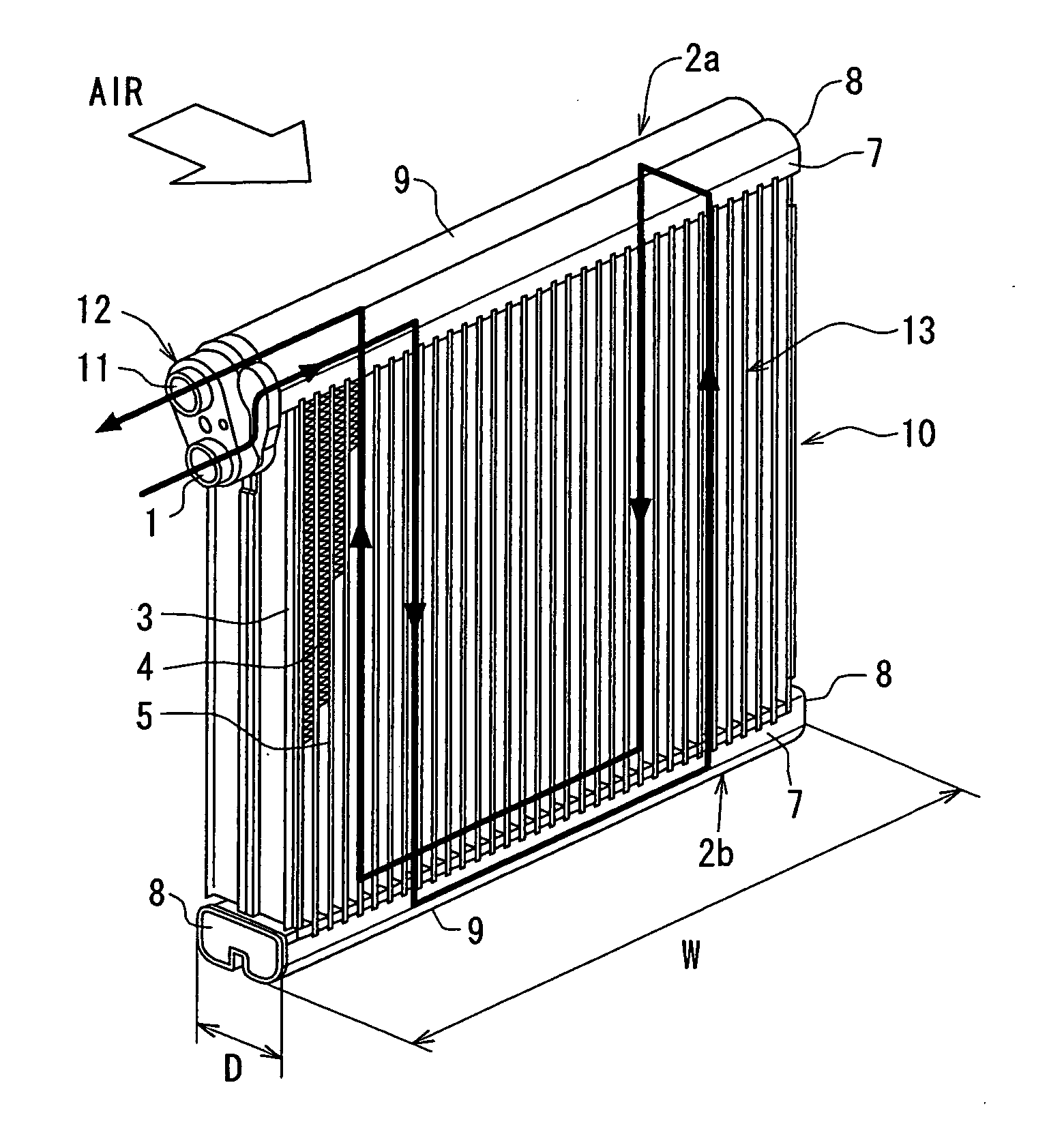
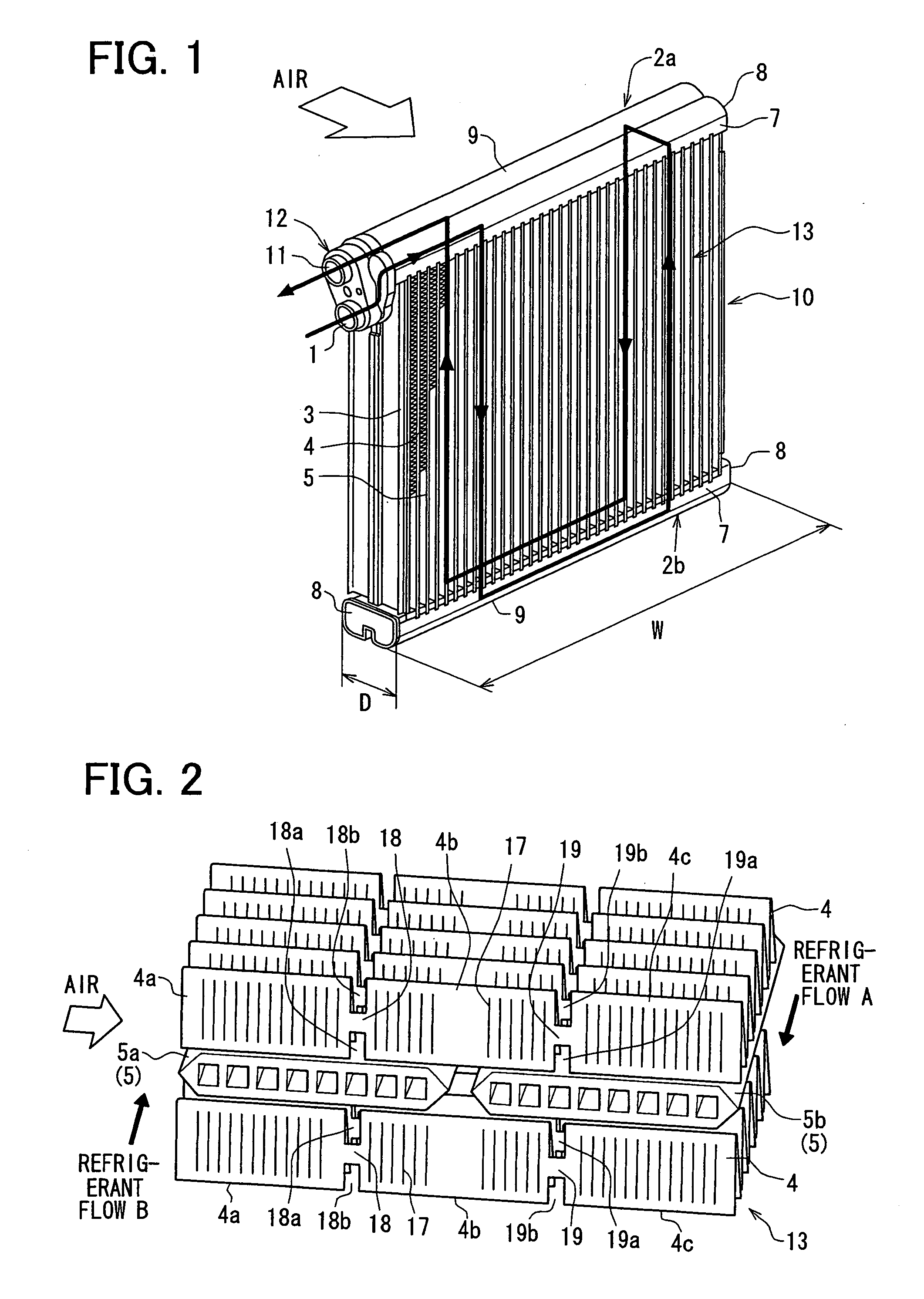
[0023] The first embodiment will be now described with reference to FIGS. 1-6. An evaporator 10 of the first embodiment is generally used in a state shown in FIG. 1, and performs heat exchange between refrigerant flowing therein and air passing therethrough.

[0024] The evaporator 10 is a part of a refrigerant cycle device that is constructed with a compressor, a refrigerant radiator, an expansion valve, etc., together with the evaporator 10. Generally, refrigerant decompressed by the expansion valve flows into the evaporator 10 from a refrigerant inlet portion 1. The refrigerant flowing into the refrigerant inlet portion 1 flows through all refrigerant paths of the evaporator 10 as in the arrows shown in FIG. 1, and then flows out of the evaporator 10 through a refrigerant outlet portion 11. Refrigerant decompressed in the expansion valve is evaporated while passing through the refrigerant paths of the core portion 13 of the evaporator 10, so that evaporated gas refrigerant flows ou...

second embodiment

[0055] The second embodiment of the present invention will be now described with reference to FIG. 7. In the second embodiment, a fin 22 is used instead of the fin 4 described in the first embodiment, and the other parts are similar to those of the above-described first embodiment. Here, the fin 22 is mainly described.

[0056] The fin 22 fixed to the tubes 5a, 5b is provided in air flow direction as shown in FIG. 7, and. is formed into a wave shape extending in the tube longitudinal direction from the first header tank 2a to the second header tank 2b. Similarly to the above-described first embodiment, plural fins 22 and the tubes 55a, 5b (5) are stacked alternately in the tube stacking direction and are brazed to form a core portion.

[0057] The fin 22 has first and second clearance portions 24, 25 each of which extends from one ridge portion of the wave-shaped fin 22 to another ridge portion of the wave-shaped fin 22 between adjacent tubes in the tube stacking direction. Therefore, t...

third embodiment

[0061] The third embodiment of the present invention will be now described with reference to FIG. 8. In the third embodiment, a fin 26 is used instead of the fin 4 described in the first embodiment, and the other parts are similar to those of the above-described first embodiment. In the third embodiment, plural slits 27a, 27b, 28a, 28b are provided at plural positions in the upstream air side area of the fin 26, upstream from the space portion between the tubes 5a, 5b in the air flow direction.

[0062] As shown in FIG. 8, the fin 26 is separated into first, second and third fin parts 26a, 26b, 26c. Specifically, the first and second fin parts 26a, 26b are partially separated from each other by first slits 27a, 27b, and the second and third fin parts 26b, 26c are partially separated from each other by second slits 28a, 28b. The first and second fin parts 26a, 26b are connected to each other by a first connection portion 27, and the second and third fin parts 26b, 26c are connected to ...


PUM


Abstract

In an evaporator, each fin is disposed between adjacent tubes in a tube stacking direction, and each of the tubes includes at least first and second tube parts lined to have a space therebetween in a flow direction of air passing between the adjacent tubes. The first tube part has therein a first refrigerant passage that is completely separately from a second refrigerant passage of the second tube part. Furthermore, the fin has at least one open portion that is opened from an end of the fin in the tube stacking direction to a predetermined portion, and the open portion is provided in the fin except for a position in the air flow direction, corresponding to the space. Therefore, the strength of the evaporator can be increased while condensed water on the evaporator can be effectively drained.

Description

CROSS REFERENCE TO RELATED APPLICATION [0001] This application is based on Japanese Patent Application No. 2005-303660 filed on Oct. 18, 2005, the contents of which are incorporated herein by reference in its entirety. BACKGROUND OF THE INVENTION [0002] 1. Field of the Invention [0003] The present invention relates to an evaporator for a refrigerant cycle device. [0004] 2. Description of the Related Art [0005] In a refrigerant evaporator for a refrigerant cycle device described in U.S. Pat. No. 6,308,527 (corresponding to JP-A-2000-179988), a fin pitch is set smaller in order to obtain a predetermined heat transferring area when the size of the evaporator is made small. However, when the fin pitch is made small, condensed water generated on the evaporator easily becomes in a water film shape on the outer surface of the evaporator by the surface tension between adjacent fin surfaces, thereby increasing a water amount staying on the outer surface of the evaporator. When the water amou...

Claims


Application Information

Patent Timeline
IPC IPC(8): F28D1/02
CPCF28D1/05391F28D2021/0071F28F1/128F28F17/005
Inventor NISHINO, TATSUHIKOKAWACHI, NORIHIDE
Owner DENSO CORP
Why Eureka
Try Eureka