Method of estimating magnetic pole position in motor and apparatus of controlling the motor based on the estimated position

a technology of motor and estimated position, applied in the direction of motor/generator/converter stopper, dynamo-electric gear control, motor/generator/converter stopper, etc., can solve the problem of large amount of calculation required to correctly, and it is difficult to downsize a motor with a position detector. problem, to achieve the effect of reducing the amount of calculation

Active Publication Date: 2007-04-19
DENSO CORP
View PDF5 Cites 41 Cited by
  • Summary
  • Abstract
  • Description
  • Claims
  • Application Information

AI Technical Summary

Benefits of technology

[0011] An object of the present invention is to provide, with due consideration to the drawbacks of the conventional estimation of a magnetic pole position, a method wherein a magnetic pole position of a rotor in a motor is accurat...

Problems solved by technology

However, it is difficult to downsize a motor with a position detector, and it is required to connect the detector with a controller for controlling the motor through connection lines.
Ho...

Method used


Image

  • Method of estimating magnetic pole position in motor and apparatus of controlling the motor based on the estimated position
  • Method of estimating magnetic pole position in motor and apparatus of controlling the motor based on the estimated position
  • Method of estimating magnetic pole position in motor and apparatus of controlling the motor based on the estimated position

Examples


embodiment 1

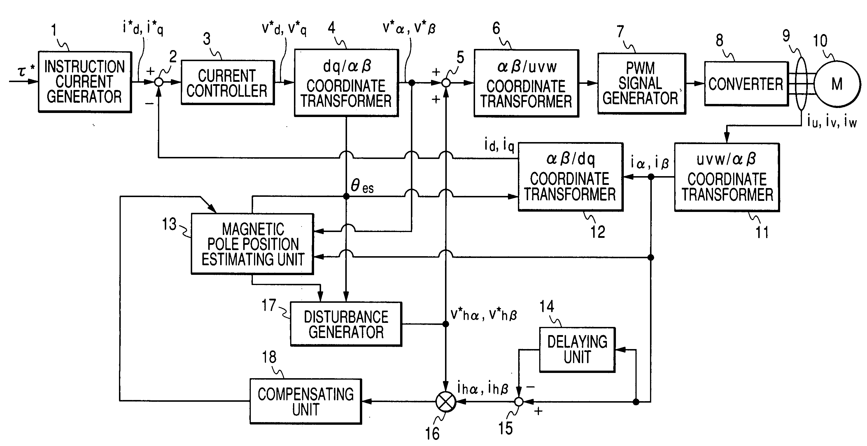
[0029]FIG. 1 is a block diagram of a control unit for a synchronous motor according to a first embodiment of the present invention.

[0030] A synchronous motor 10 shown in FIG. 1 has windings of a stator and a rotor (not shown) made of permanent magnets. When a three-phase alternating current voltage is applied to the windings, a three-phase alternating current composed of phase currents of U, V and W phases flows through the windings so as to generate a changeable magnetic field due to electromagnetic induction, and the rotor having the permanent magnets is rotated on its rotation axis in response to the magnetic field. The rotational force is outputted through a transmitter such as a pulley and a belt. A phase of the current is controlled in a control unit shown in FIG. 1 to stably rotate the rotor at a desired rotational speed.

[0031] In this embodiment, permanent magnets having salient poles are disposed around a shaft of a rotor so as to be protruded from the shaft, so that a d-...

first modification

of First Embodiment

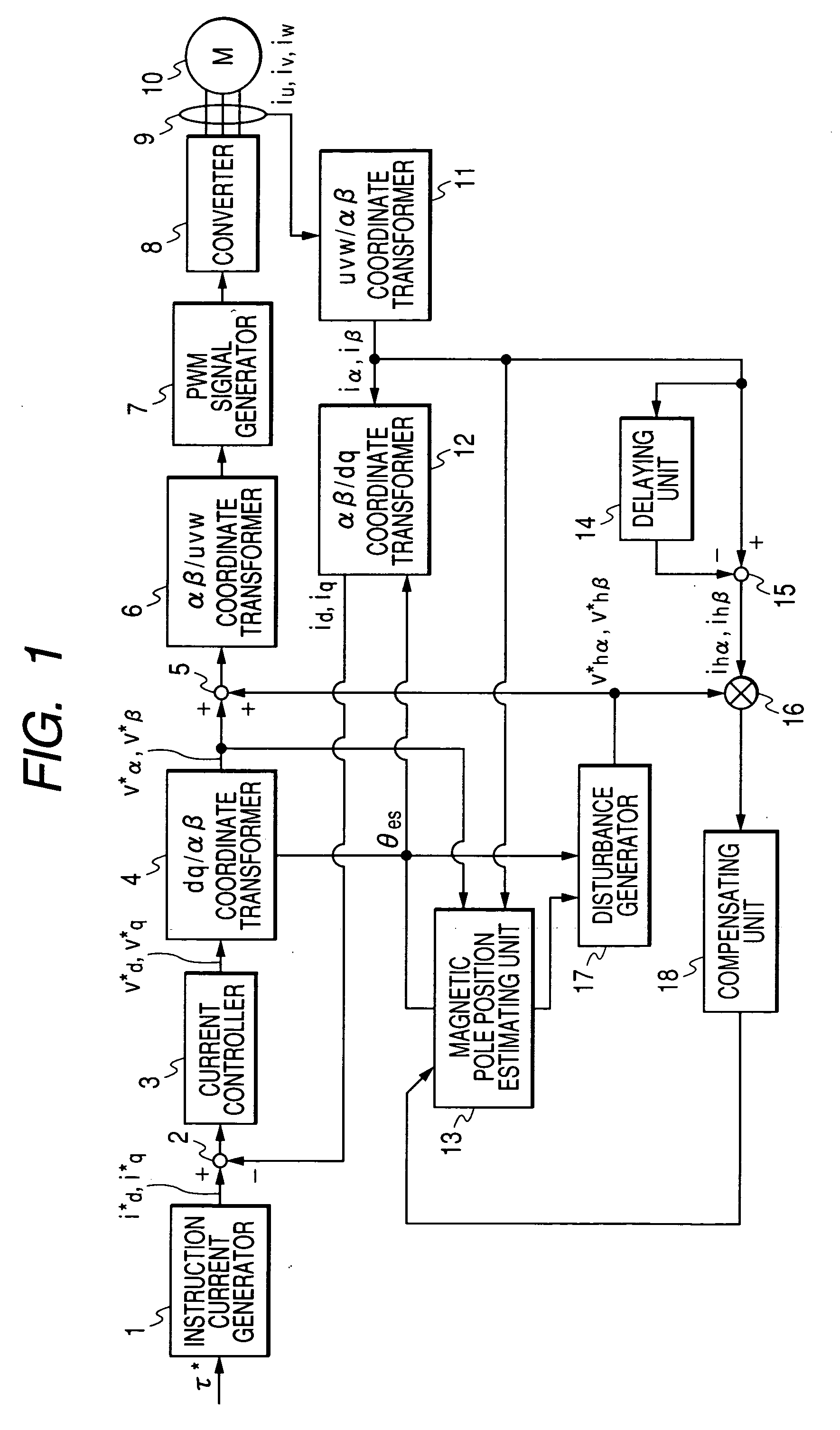
[0071] In the first embodiment, the phase matching voltage V*h(V*hα, V*hβ) and the phase matching current ih(ihα, ihβ) are defined in the αβ stationary coordinates system. However, a magnetic pole position may be estimated such that an outer product of a phase matching voltage and a phase matching current defined in the dq rotational coordinates system substantially becomes zero.

[0072]FIG. 3 is a block diagram of a control unit for a synchronous motor according to a first modification of the first embodiment.

[0073] As shown in FIG. 3, the disturbance generator 17 generates a d-axis component V*hd of a phase matching voltage such that a phase of the phase matching voltage matches with that of the estimated position θes. Because the position θes correctly estimated substantially matches with a true position θc placed on the d-axis, the phase matching voltage is generated such that the phase of the phase matching voltage matches with the d-axis. That is, the phase ...

second modification

of First Embodiment

[0076] An applied phase matching current having only a d-axis component may be superimposed on the d-axis difference Δid outputted from the calculator 2. In this case, the disturbance generator 17 generates the phase matching current having the same phase as that of an estimated magnetic pole position which substantially matches with a true magnetic pole position. The controller 3 converts the phase matching current into a phase matching voltage having the same phase as the phase matching current. The phase matching voltage is applied to the motor 10, and the calculator 15 extracts a phase matching current ih(ihd, ihq) generated from the applied phase matching current from the detected alternating current.

[0077] Therefore, the phase matching voltage superimposed on the instructed voltage is substantially applied to the motor, and the q-axis inductance Lq. can be corrected such that an outer product of the applied phase matching current and the phase matching curr...


PUM


Abstract

A magnetic pole position in a synchronous motor having salient poles is estimated from an instructed voltage applied to the motor, a current generated from the instructed voltage and parameters. To estimate the position substantially matching with a true magnetic pole position, a phase matching voltage having a phase matching with the estimated magnetic pole position previously obtained is applied to the motor. The phase matching voltage has a harmonic frequency higher than that of the instructed voltage. A phase matching current generated from the phase matching voltage is detected from the motor. A value of at least one of the parameters is corrected such that a difference in phase between the phase matching voltage and the phase matching current substantially becomes zero. An estimated magnetic pole position is calculated from the instructed voltage, the generated current and the parameter having the corrected value.

Description

CROSS-REFERENCE TO RELATED APPLICATION [0001] This application is based upon and claims the benefit of priority of the prior Japanese Patent Application 2005-299242 filed on Oct. 13, 2005 so that the contents of which are incorporated herein by reference. BACKGROUND OF THE INVENTION [0002] 1. Field of the Invention [0003] The present invention relates to a method of estimating a position (e.g., magnetic pole position) of a rotor in a synchronous motor and an apparatus of controlling the motor based on the estimated position. [0004] 2. Description of Related Art [0005] In a synchronous motor such as a surface permanent-magnetic synchronous motor (SPMSM) or an internal permanent-magnetic synchronous motor (IPMSM), permanent magnets are used for a rotor, and S and N magnetic poles formed by the permanent magnets are alternately disposed around a rotor shaft. During the operation of this motor, an alternating current voltage is applied to windings of a stator, and an alternating current...

Claims


Application Information

Patent Timeline
IPC IPC(8): H02P1/46H02P6/06H02P6/18H02P6/08H02P6/182H02P6/28H02P21/00H02P21/13H02P21/14H02P21/18H02P21/22H02P21/24H02P21/28H02P23/12H02P23/14H02P27/04H02P27/08
CPCH02P6/185H02P21/0042H02P21/146H02P2207/05H02P21/26H02P21/18
Inventor FUJITSUNA, MASAMIIMURA, AKIHIRO
Owner DENSO CORP
Why Eureka
Try Eureka