Preventing flicker effects in video electronic devices

a technology of electronic devices and video cameras, applied in the direction of signal generators with optical-mechanical scanning, television systems, color signal processing circuits, etc., can solve the problems of certain limitations of using this method and certain weak points of digital cameras under artificial lighting conditions, and achieve the effect of preventing flickering effects

Active Publication Date: 2007-04-19
NOKIA TECHNOLOGLES OY
View PDF9 Cites 39 Cited by
  • Summary
  • Abstract
  • Description
  • Claims
  • Application Information

AI Technical Summary

Benefits of technology

[0006] According to a first aspect of the invention, a method for preventing a flicker effect in an electronic device, comprises the steps of: determining whether a flicker light source is present; activating an optical intensity reducing block in the electronic device if the flicker light source is present and pr...

Problems solved by technology

Digital cameras have a certain weak point under artificial ligh...

Method used


Image

  • Preventing flicker effects in video electronic devices
  • Preventing flicker effects in video electronic devices
  • Preventing flicker effects in video electronic devices

Examples


Embodiment Construction

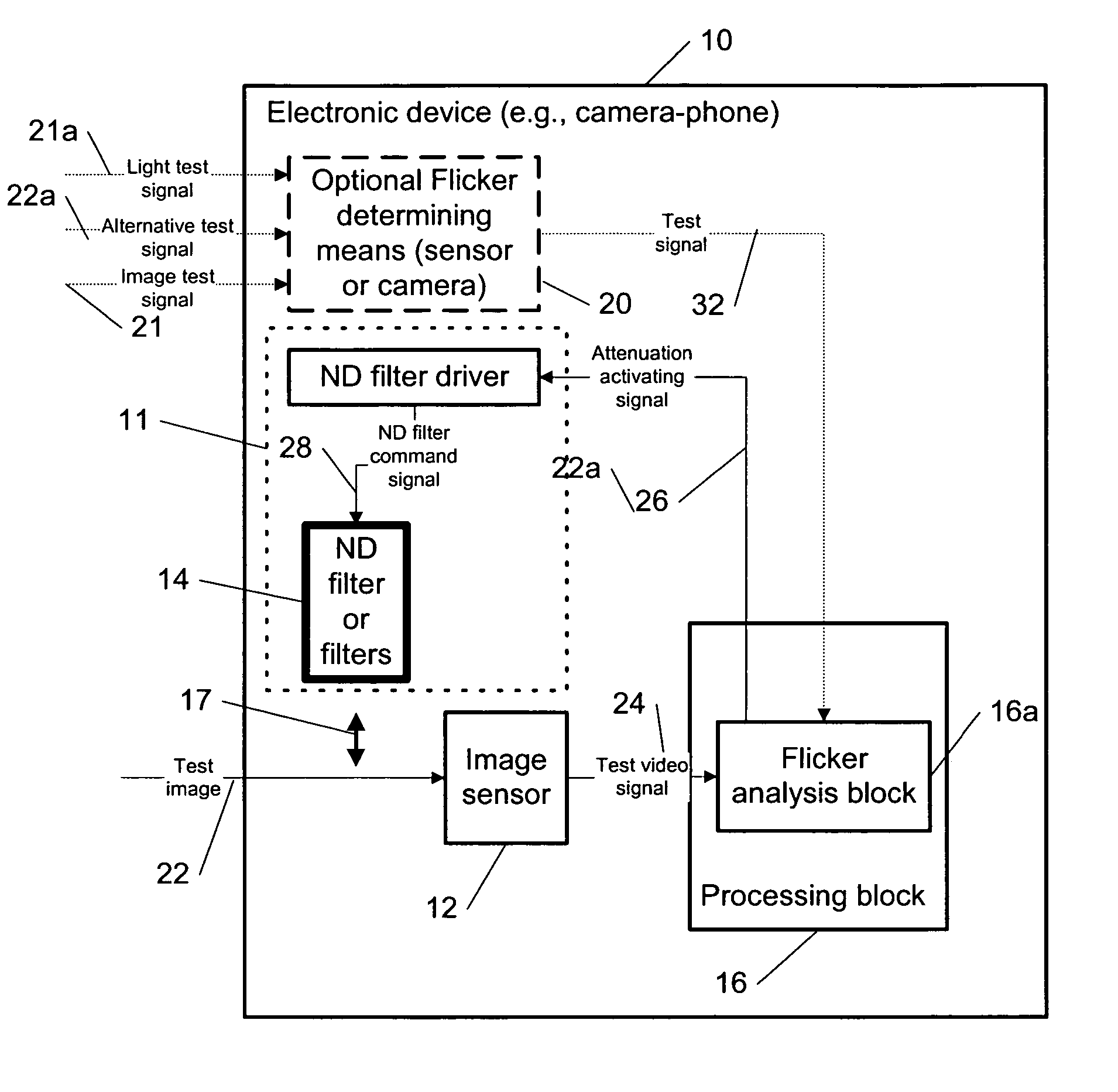
[0034] A new method, apparatus and software product are presented for reducing flicker effects in electronic devices (e.g., a video camera, a digital camera, a digital video camera, a camera-phone mobile device, a wireless communication device, a portable electronic device, etc.) by reducing an optical intensity of a video image received by the electronic device.

[0035] According to an embodiment of the present invention, it is determined by the electronic device whether a flicker light source is present and predetermined conditions (e.g., related to a light level, to a shortest exposure time, etc.), as described below in detail, are met. If the flicker light source is present and the predetermined conditions are met, then an optical attenuation of a video image taken by the electronic device is provided (e.g., by an optical intensity reducing block) using a predetermined criterion and a video signal of the video image is generated by the electronic device using an exposure time sub...


PUM


Abstract

The specification and drawings present a new method, apparatus and software product for reducing flicker effects in electronic devices (e.g., a video camera, a camera-phone mobile device, a portable electronic device, etc.) by reducing an optical intensity of a video image received by the electronic device. It is determined by the electronic device whether a flicker light source is present and if predetermined conditions are met. As long as that is the case, an optical attenuation of a video image taken by the electronic device is provided using a predetermined criterion and a video signal of the video image is generated by the electronic device using an exposure time substantially equal to or a multiple of an inverse of a flicker frequency.

Description

TECHNICAL FIELD [0001] The present invention relates generally to video electronic devices and, more specifically, to reducing flicker noise effects in video cameras and related electronic devices. BACKGROUND ART [0002] Digital cameras have a certain weak point under artificial lighting conditions. Lighting which is working under AC electrical system is flickering at two times higher frequency than the electricity frequency is. There are two dominant electric frequency systems in the world: 50 Hz and 60 Hz. Electricity has both negative and positive half of a sinusoidal wave. When such electric signal is used for lighting, light automatically rectifies the signal and the output light has a frequency of 2×50 Hz=100 Hz (e.g., in Europe) or 2×60 Hz=120 Hz (e.g., in the United States). The flicker can be modelled, e.g., using functions of cos2 or abs(cos). [0003]FIG. 1 shows frequency comparison between electricity and light: base electric frequency ‘f’, and light frequency ‘2f’. Freque...

Claims


Application Information

Patent Timeline
IPC IPC(8): H04N9/73H04N7/01H04N11/20G02B5/20H04N5/228H04N5/357
CPCH04N5/2351H04N5/2353H04N5/2357H04N23/745H04N23/73H04N23/71
Inventor HAKOLA, MANUKAKKORI, HANNU
Owner NOKIA TECHNOLOGLES OY
Why Eureka
Try Eureka