Interferometric beam combination

a fiber amplifier and interferometer technology, applied in lasers, instruments, manufacturing tools, etc., can solve the problems of inability to achieve sbsa, especially a fiber array, to achieve the effect of maximizing the power delivered to the composite output beam, minimizing losses, and maximizing power delivered

Active Publication Date: 2007-04-19
NORTHROP GRUMMAN SYST CORP
View PDF6 Cites 31 Cited by
  • Summary
  • Abstract
  • Description
  • Claims
  • Application Information

AI Technical Summary

Benefits of technology

[0008] sampling the composite output beam and detecting its phase in a single heterodyne detector; deriving from the detector a measure of phase for each of the emitter signals relative to a common reference, as identifiable by the dithering signal frequencies; and applying phase corrections to the separate emitters to maintain phase coherency among the emitter outputs and thereby to maximize power delivered in the composite output beam.
[0009] In a third embodiment of the invention, beams from the N emitters are generated from a master oscillator connected to a binary tree of multiple emitter stages of beam splitters and emitters; and pairs of emitters at each emitter stage are anti-symmetrically phase modulated. The step of providing a succession of beam splitters and associated mirrors comprises providing a binary tree of beam-combining splitters in which outputs from the multiple emitter stages are combined. Each stage of the beam-combining splitters produces one or more combined output ...

Problems solved by technology

The performance of such arrays is, however, significantly limited by the necessarily low “fill factor” of the array.
A Strehl ratio of unity or 100% is indicative of an ideal beam, but this cannot be achieved in an SBSA, especially a fiber array, because the fill factor is generall...

Method used


Image

  • Interferometric beam combination
  • Interferometric beam combination
  • Interferometric beam combination

Examples


Embodiment Construction

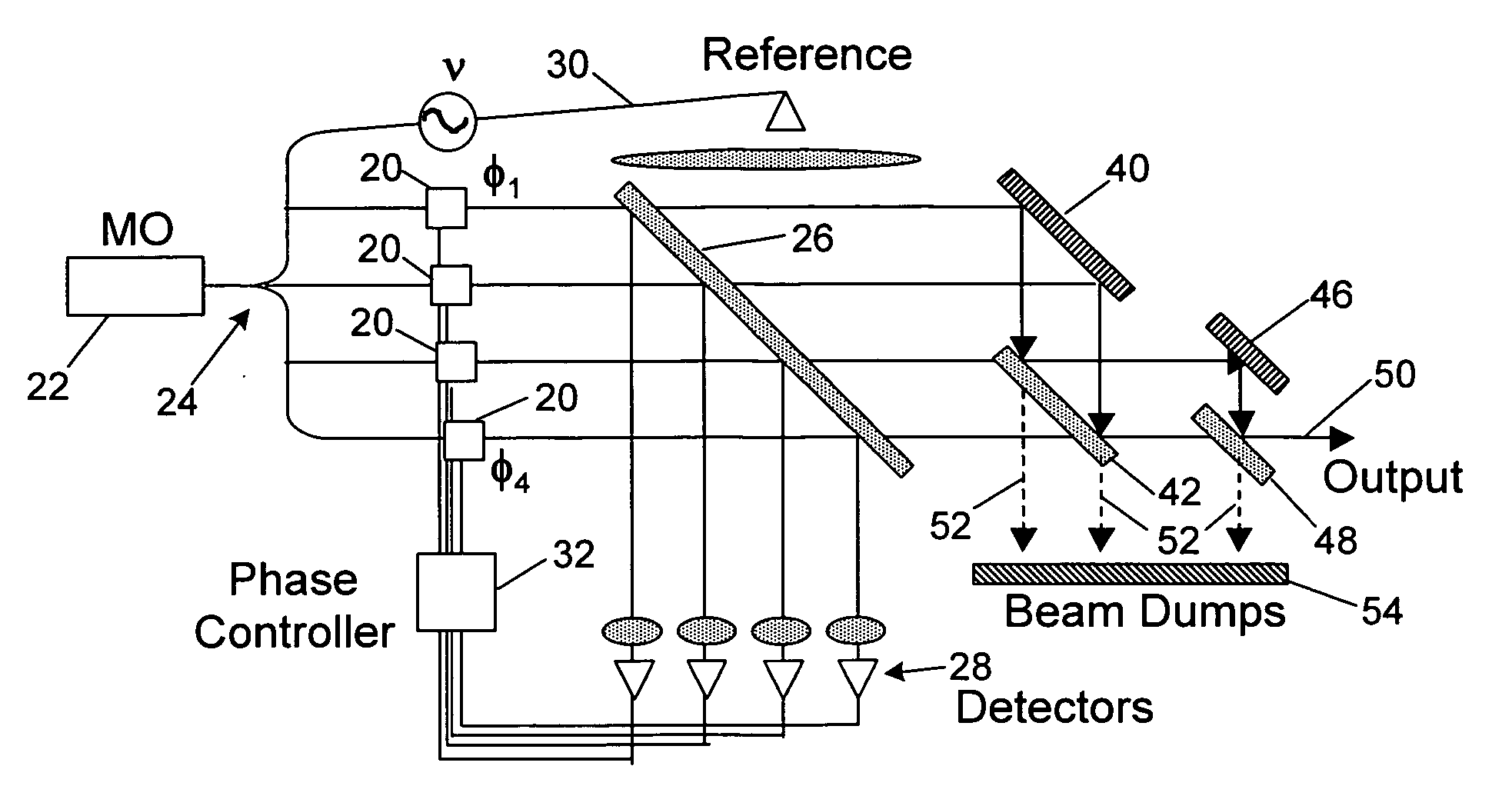
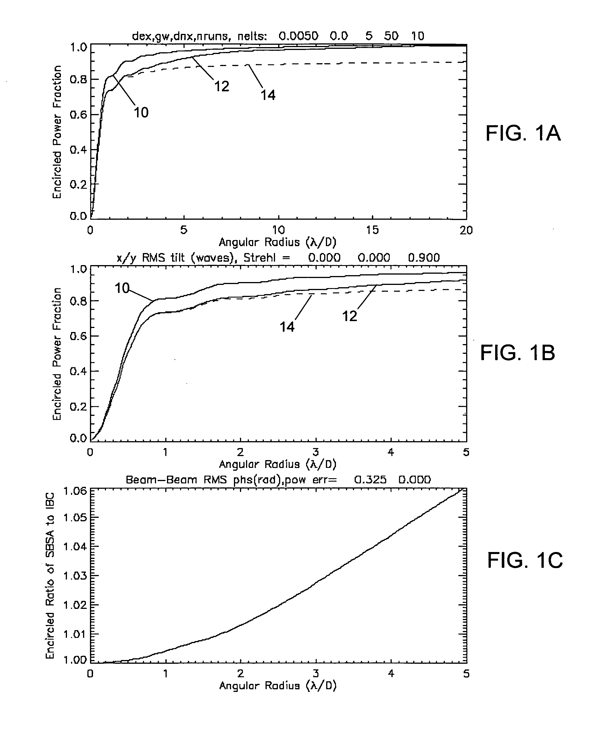
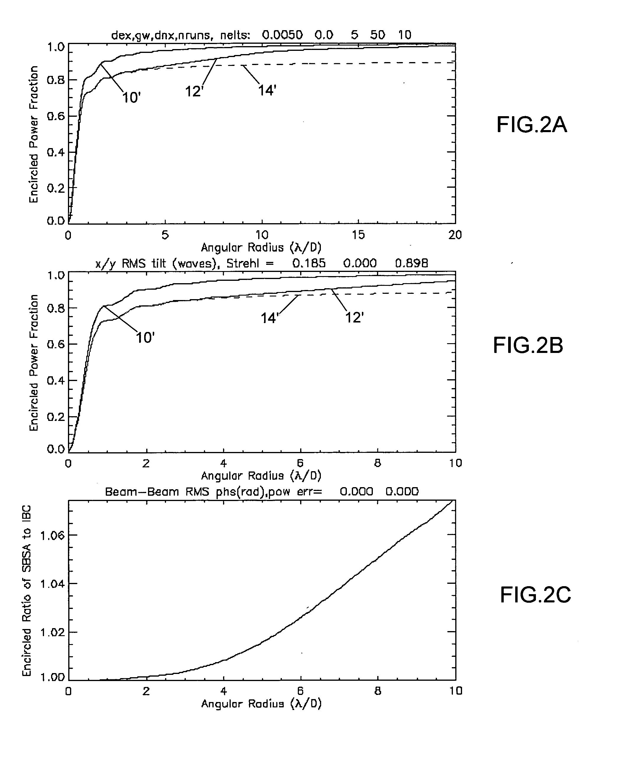
[0020] As shown in the drawings for purposes of illustration, the present invention is concerned with combining the radiation emitted from multiple emitters in an array to produce a powerful composite beam having good performance characteristics, as measured, for example, by the Strehl ratio of the beam. The use of side-by-side arrays (SBSAs) of fibers necessarily results in a reduced Strehl ratio because of the less than ideal fill factor associated with closely packed fibers, and the peaked beam profile provided by each fiber. Another drawback of the prior art approaches to combining multiple coherent beams is that any alignment or other phase errors tend to be propagated through the entire optical system.

[0021] In accordance with the present invention, multiple beams are interferometrically combined in the near field (interferometric beam combination, or IBC), using any of a variety of optical techniques. IBC of N beams can be accomplished with a minimum of m beam splitters, whe...


PUM

PropertyMeasurementUnit
Ratioaaaaaaaaaa
Phaseaaaaaaaaaa

Abstract

A method for combining beams from multiple laser emitters, which may be optical fibers or bulk amplifiers, to form a composite output beam with desirable beam characteristics, as measured, for example, by Strehl ratio. Beams from the multiple emitters are interferometrically combined in the near field, and the phases of the beams are controlled to provide optimal phase coherence, and thereby to minimize losses. Various techniques are disclosed for controlling the phase angles of the emitted beams, using either a separate phase detector for each emitter beam, or a single detector for the composite output beam, or nulling detectors in spurious outputs from the beam combining optics. All of these techniques achieve an improvement in Strehl, largely because the interferometric combination of beams is independent of the array fill factor.

Description

BACKGROUND OF THE INVENTION [0001] This invention relates generally to high power lasers and, more particularly, to arrays of fiber amplifiers configured to produce a powerful composite beam. Typically, radiation emitting fibers are arranged in two-dimensional array, referred to as a side-by-side array (SBSA), in which the phases of emitters are controlled render them mutually coherent. The beams combine in the far field as they diverge and diffract, forming the composite beam. The performance of such arrays is, however, significantly limited by the necessarily low “fill factor” of the array. Even if the fibers, which are cylindrical in shape, are closely packed in a hexagonal pattern, the fill factor is reduced by the spaces between adjacent fibers. One measure of the optical performance of such an array is the Strehl ratio of the composite beam, defined as the ratio of the on-axis intensity of the beam to the on-axis intensity that would have been obtained with a diffraction limit...

Claims


Application Information

Patent Timeline
IPC IPC(8): G01B9/02
CPCB23K26/0613B23K26/426H01S3/06754H01S3/1301H01S3/1307H01S3/2383B23K26/705
Inventor ROTHENBERG, JOSHUA E.
Owner NORTHROP GRUMMAN SYST CORP
Why Eureka
Try Eureka