Broadband cavity spectrometer apparatus and method for determining the path length of an optical structure

a narrowband cavity and optical path technology, applied in the field of broadband cavity spectrometer apparatus and methods for measuring the optical path length in optical cavities, can solve the problems of not being able to use a single wavelength technique, detecting changes, and determining the absolute value of the optical path length, so as to add to the ease of tracking the optical path

Inactive Publication Date: 2007-04-19
INTELLECTUAL VENTURES HLDG 40
View PDF7 Cites 33 Cited by
  • Summary
  • Abstract
  • Description
  • Claims
  • Application Information

AI Technical Summary

Benefits of technology

[0007] The Fourier transform of the spectrum will contain a DC peak and at least one other peak that is related to the OPL. The certainty that the Fourier transform of the spectrum of the light reflected from or transmitted through the optical cavity has a peak located at a coordinate equal to twice the OPL is a key feature of the present invention. By locating and tracking the position of this peak, one is able to measure and track the OPL directly. Due to the nature of the spectrum of the light reflected from the optical cavity, this OPL peak will be the most prominent one aside from the DC peak (whose location is known). This feature adds to the ease of tracking the OPL with the Fourier transform. If efficient Fourier algorithms are used with sufficiently fast computer technology, the OPL may be tracked in real-time, for example, during a manufacturing process.

Problems solved by technology

In such cases, the S / N will be small and thus may not be sufficient to use a single wavelength technique.
Therefore, a single-wavelengh system cannot determine the absolute value of the optical path length, it can only detect changes.
The change in optical path length as measured by a single-wavelengh system is sufficient for some servo applications where the path length is to be held constant; however, this allows the possibility of mode-hopping where the servo unintentionally and undesirably locks onto a different spectral mode.

Method used


Image

  • Broadband cavity spectrometer apparatus and method for determining the path length of an optical structure
  • Broadband cavity spectrometer apparatus and method for determining the path length of an optical structure
  • Broadband cavity spectrometer apparatus and method for determining the path length of an optical structure

Examples


Embodiment Construction

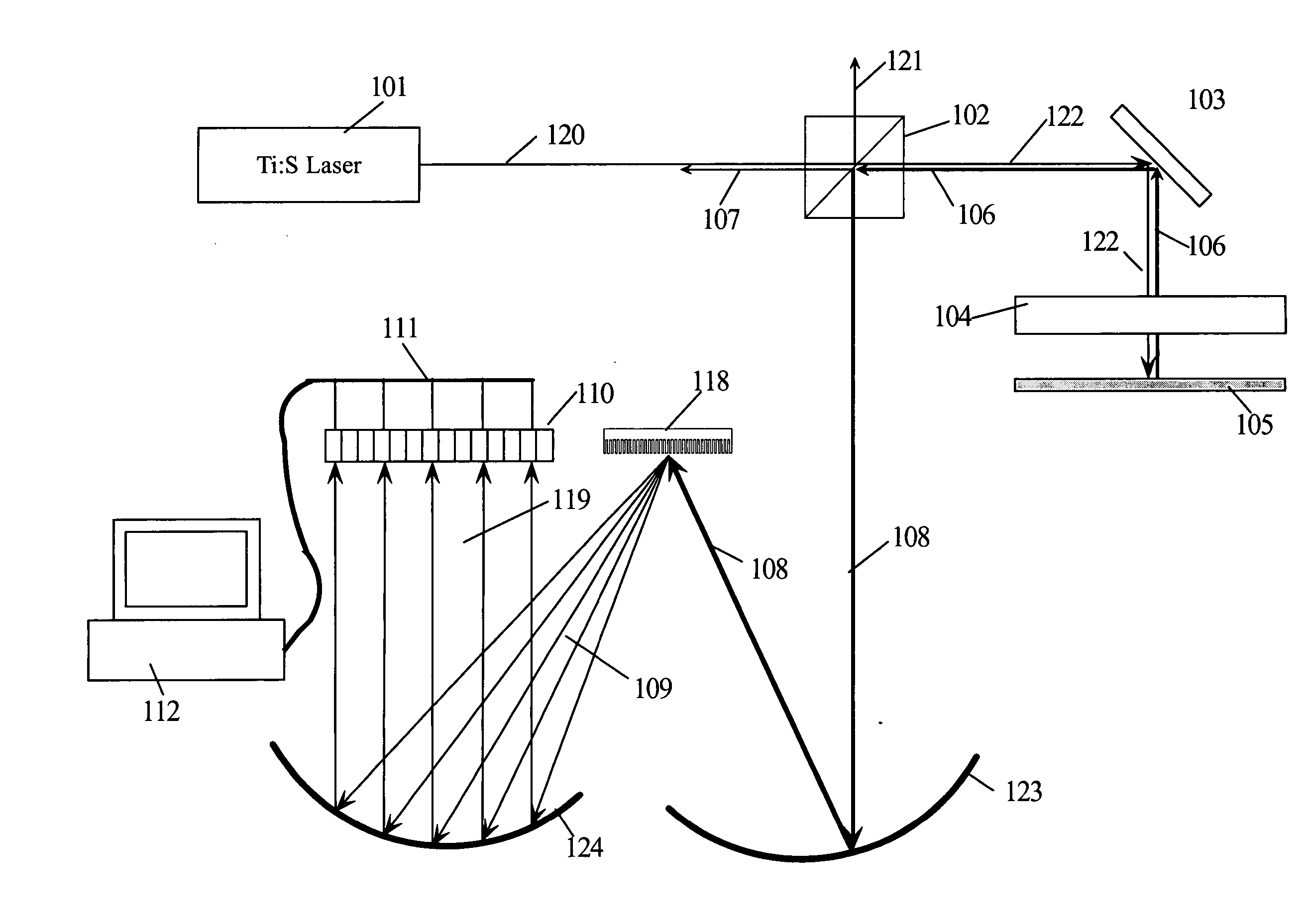
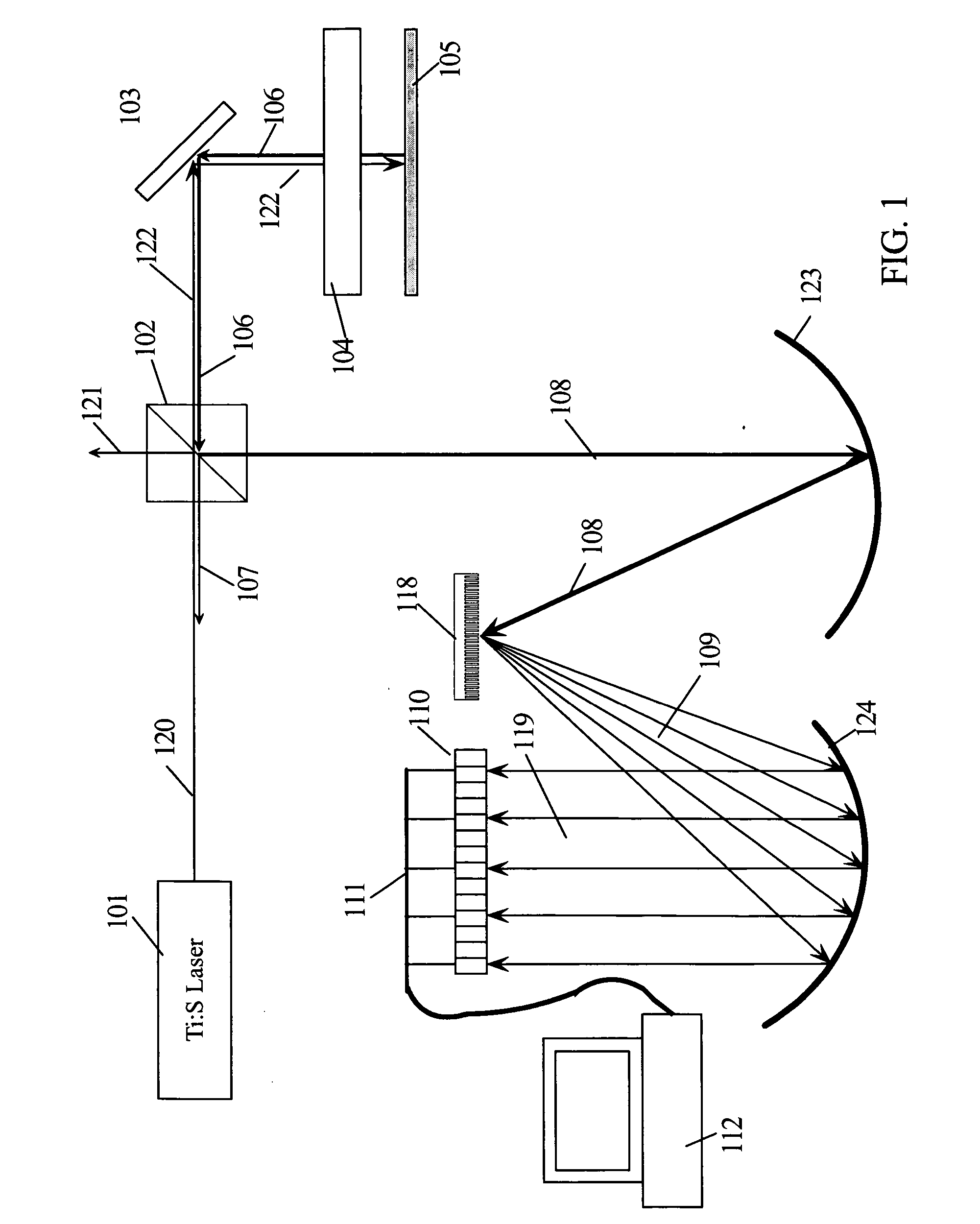
[0015] In the following description, numerous specific details are set forth to provide a thorough understanding of the present invention. For example, specific subsystems and functions may be described; however, it would be recognized by those of ordinary skill in the art that the present invention may be practiced without such specific details. In other instances, well-known units or systems have been shown in block diagram form in order not to obscure the present invention in unnecessary detail. Refer now to the drawings wherein depicted elements are not necessarily shown to scale and wherein like or similar elements are designated by the same reference numeral by the several views.

[0016] In the following detailed description, a variable may be referred to as having a DC (direct current) component, wherein the variable may not be electrical current. In these cases, DC means that the variable has a static non-changing component. The variable may also have a sinusoidal component w...


PUM


Abstract

A broadband light source with a sufficiently long coherence length is impinged on the optical cavity. The broadband laser light reflects from the first and second surfaces of the cavity. The two light beams, either reflected or transmitted, are phase shifted from one another by an amount proportional to the optical path length of the cavity and inversely proportional to the wavelength of the light (4πnd/λ) The two light beams interfere with each other and form a modulated light beam that has a spectrum approximately like the laser's broadband spectrum multiplied by a cosine with a frequency 4πnd/λ. The modulated light beam is coupled to a spectrometer that measures the intensity of the light as a function of wavelength over a range of wavelengths. The Fourier transform of the spectrum contains a peak that is related to the OPL and is located at 2*n*d where n*d is the OPL.

Description

TECHNICAL FIELD [0001] The present invention relates to apparatus and methods for measuring the optical path length in optical cavities. BACKGROUND INFORMATION [0002] An optical cavity may be any region bounded by two or more reflective interfaces that are aligned to provide multiple reflections of light waves. Optical cavities have been monitored or measured using a single wavelength illumination source such as a helium / neon (HeNe) laser. A change in the cavity size is detected by observing the change in reflected or transmitted intensity at the single wavelength. Monitoring a single wavelength reflected intensity requires a much larger signal-to-noise ratio (S / N) than a broadband technique. In certain applications, the cavity is filled with a fluid that is designed to have an index of refraction as close as possible to that of the bounding surfaces, making the reflectivity very small. In such cases, the S / N will be small and thus may not be sufficient to use a single wavelength te...

Claims


Application Information

Patent Timeline
Patent Type & Authority Applications(United States)
IPC IPC(8): G01B11/02G01B9/02G01J3/45
CPCG01B9/02044G01B9/02057G01B9/0209
Inventor SHIH, CHIH-KANGWIELAND, CHRISTOPHER FRANKFLAGG, EDWARD BRADSTREET
Owner INTELLECTUAL VENTURES HLDG 40
Why Eureka
Try Eureka