Side emitting illumination systems incorporating light emitting diodes

a technology of light-emitting diodes and side-emitting illumination, which is applied in the direction of lighting and heating apparatus, instruments, display means, etc., can solve the problems of increasing the output brightness and efficiency of the side-emitting illumination system, the edge brightness of the led light source is no longer convenient to place led light sources along the edge of the waveguide, and the cost of solid plastic waveguides is high. , to achieve the effect of increasing the effective brightness of the light-e-

Inactive Publication Date: 2007-04-19
GOLDENEYE
View PDF13 Cites 216 Cited by
  • Summary
  • Abstract
  • Description
  • Claims
  • Application Information

AI Technical Summary

Benefits of technology

[0016] One embodiment of this invention is a side-emitting illumination system that is comprised of a light emitting diode, a first reflector surrounding the light emitting diode, a second reflector that is separated from and opposite the first reflector and the light emitting diode, wherein the second reflector has an edge. The output aperture of the side-emitting illumination system is formed by the first reflector and the edge of the second reflector. A supporting means holds and separates the second reflector from the first reflector. The light emitting diode is comprised of a first doped semiconductor layer having an output surface, a second doped semiconductor layer, an active region interposed between the first doped semiconductor layer and the second doped semiconductor layer wherein the active region has electrical contact with both the first doped semiconductor layer and the second doped semiconductor layer, a first reflecting electrode in electrical contact with the first doped semiconductor layer and a second reflecting electrode in electrical contact with the second doped semiconductor layer. The first doped semiconductor layer and the second doped semiconductor layer have opposite n and p conductivity types. The active region of the light emitting diode emits internally generated light through the output surface of the first doped semiconductor layer when a voltage is applied between the first reflecting electrode and the second reflecting electrode. The internally generated light emitted through the output surface is directed to the second reflector of the side-emitting illumination system or is directed through the output aperture of the side-emitting illumination system. Internally generated light that is reflected by the second reflector is redirected through the output aperture of the side-emitting illumination system or is redirected to the first reflector or is recycled back to the light emitting diode as externally incident light. A portion of the externally incident light recycled back to the light emitting diode is reflected by the first reflecting electrode and the second reflecting electrode of the light emitting diode, thereby increasing the effective brightness of the light emitting diode, and is subsequently directed through the output aperture, thereby increasing the output brightness and efficiency of the side-emitting illumination system. The light emitting diode reflects externally incident light with a reflectivity greater than 40 percent.

Problems solved by technology

As the backlight become larger, it is no longer convenient to place LED light sources along the edges of the waveguide.
When the LEDs are placed only along the edges of the waveguide, the edges of the display may be brighter than the center of the display, which is undesirable.
For a very large LCD television such as a 37-inch or larger diagonal display, the solid plastic waveguide becomes very heavy and expensive.
In addition, the plastic material such as acrylic that is used for the waveguide absorbs a considerable amount of blue light.
However, the air filled box still needs to be thin.
For example, GaN-based LEDs with a silicon carbide substrate are usually poor light reflectors with an overall reflectivity of less than 40%.
An additional reason for the low reflectivity of many present LED designs is that the external structures on the LEDs, including the top metal electrodes, metal wire bonds and sub-mounts to which the LEDs are attached, are not designed for high reflectivity.
Any light that is directed toward a poorly reflecting LED may be absorbed and lower the overall efficiency of the illumination system.
Some types of LEDs exist that have relatively high reflectivity, but such LEDs generally have low light extraction efficiency (for example, less than 25%).
Illumination systems designed with such LEDs have low overall efficiency due to the low extraction efficiency of light from the LED structure.

Method used


Image

  • Side emitting illumination systems incorporating light emitting diodes
  • Side emitting illumination systems incorporating light emitting diodes
  • Side emitting illumination systems incorporating light emitting diodes

Examples


Embodiment Construction

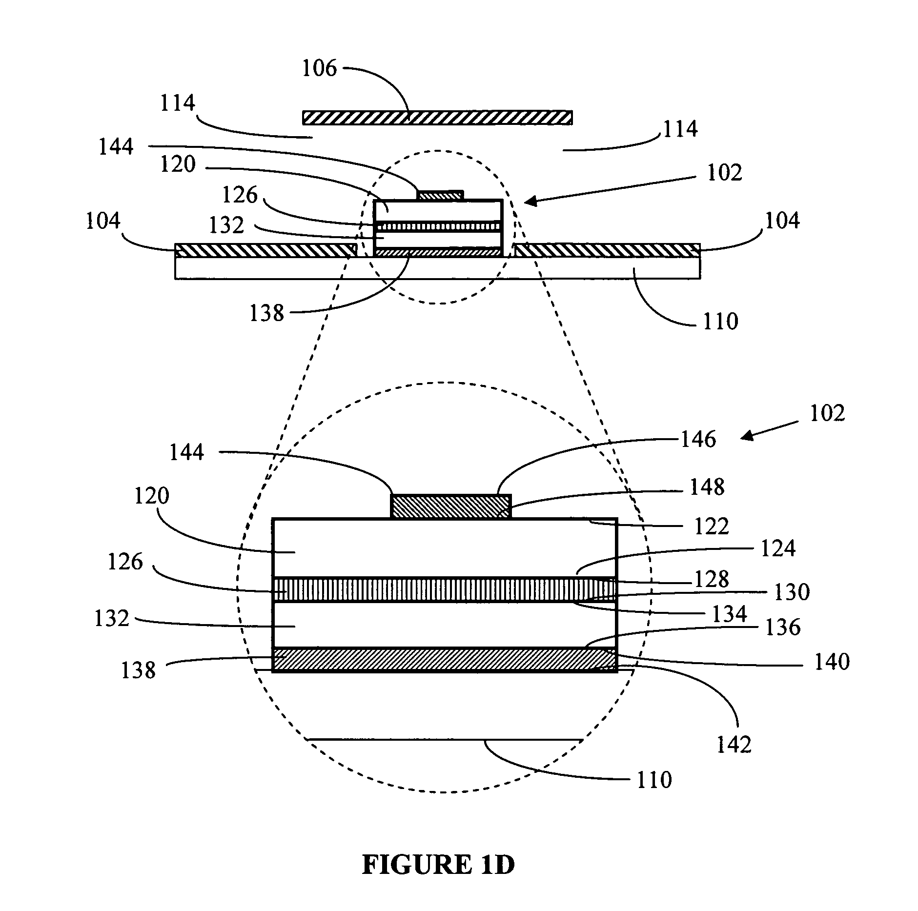
[0037] The preferred embodiments of the present invention will be better understood by those skilled in the art by reference to the above listed figures. The preferred embodiments of this invention illustrated in the figures are not intended to be exhaustive or to limit the invention to the precise form disclosed. The figures are chosen to describe or to best explain the principles of the invention and its applicable and practical use to thereby enable others skilled in the art to best utilize the invention. The above listed figures are not drawn to scale. In particular, the thickness dimension of the LEDs is expanded to better illustrate the various internal layers of the devices.

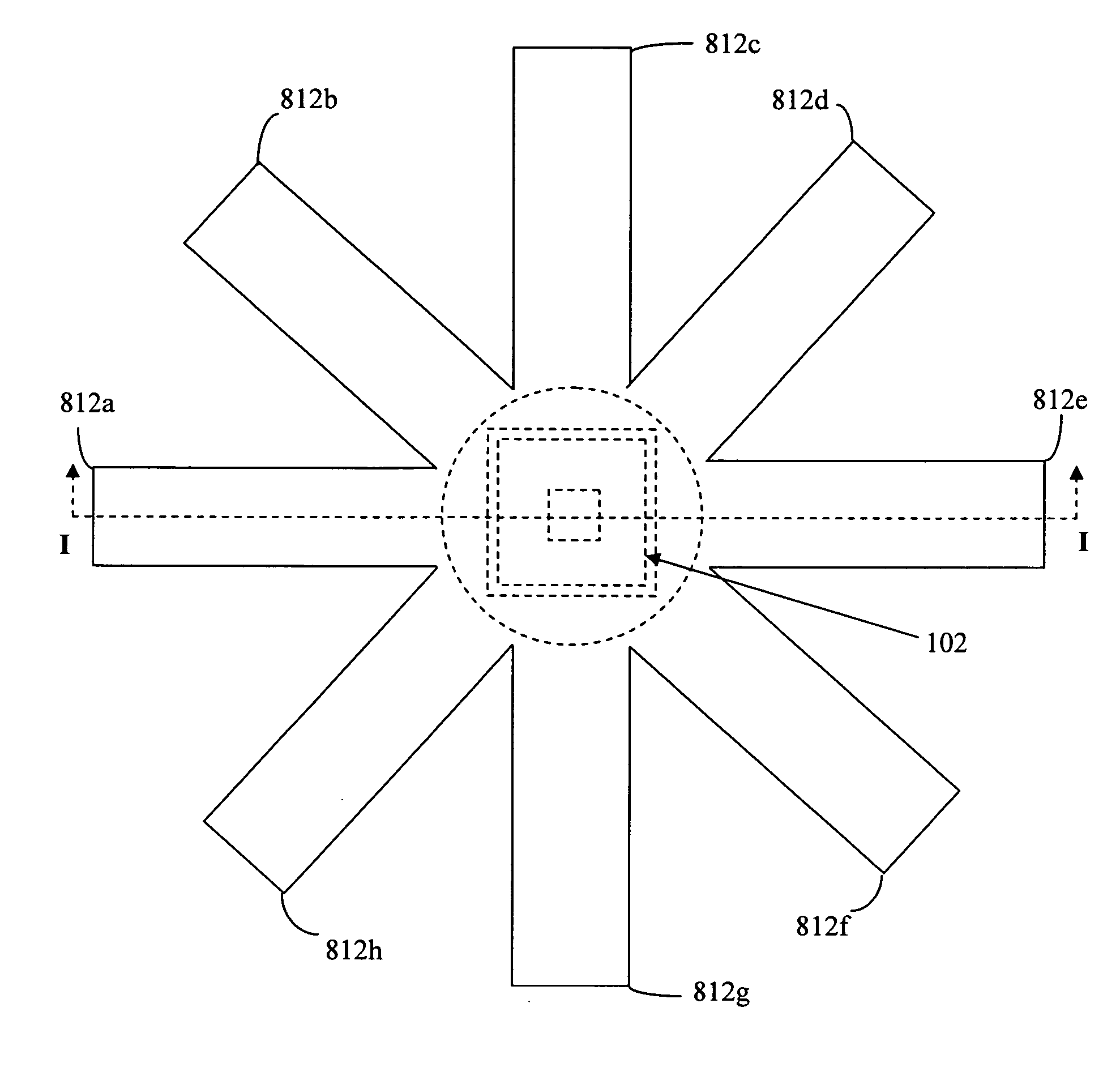
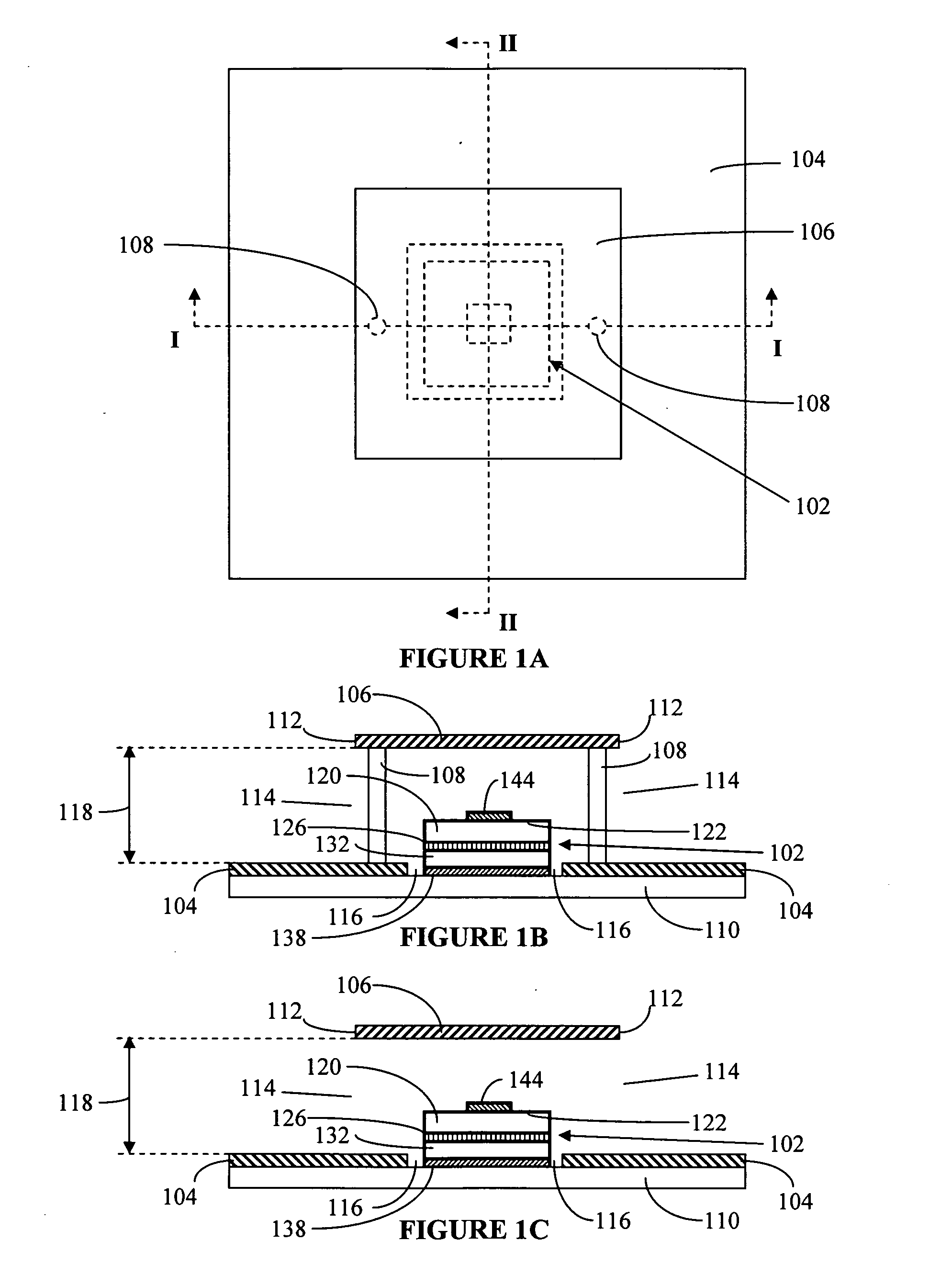
[0038] One embodiment of this invention is illustrated in FIGS. 1A-1I. FIG. 1A is a top plan view of side-emitting illumination system 100. FIG. 1B is a cross-sectional view along the I-I plan of the side-emitting illumination system 100 illustrated in FIG. 1A. FIG. 1C is a cross-sectional view along the ...


PUM


Abstract

The invention is a side-emitting illumination system that incorporates a light emitting diode. The side-emitting illumination system recycles a portion of the light internally generated by a light emitting diode back to the light emitting diode as externally incident light. The light emitting diode reflects the recycled light, thereby increasing the effective brightness of the light emitting diode. The light reflected by the light emitting diode is directed though the output aperture of the side-emitting illumination system, thereby increasing the output brightness and efficiency of the side-emitting illumination system. The light emitting diode reflects externally incident light with a reflectivity greater than 40 percent.

Description

CROSS REFERENCE TO RELATED APPLICATION [0001] This application is related to U.S. patent application Ser. No. ______ entitled “LIGHT EMITTING DIODE WITH A SIDE EMITTING LENS”, which is filed concurrently with this application and which is herein incorporated by reference.TECHNICAL FIELD [0002] The present invention is a side emitting illumination system that incorporates one or more light emitting diodes. BACKGROUND [0003] Light emitting diodes (LEDs) are rapidly replacing incandescent and fluorescent light sources in many illumination systems. LEDs emit light in the ultraviolet, visible and infrared regions of the optical spectrum. Gallium nitride (GaN) based LEDs, for example, emit light in the ultraviolet, blue, cyan and green spectral regions. AlGaInP LEDs emit light in the yellow and red regions of the optical spectrum. [0004] Some illumination applications require a thin, low profile structure. For example, a backlight for a liquid crystal display (LCD) on a laptop computer or...

Claims


Application Information

Patent Timeline
Patent Type & Authority Applications(United States)
IPC IPC(8): F21V7/04
CPCG02F1/133603G02F2001/133614H01L25/0753H01L33/60Y10S362/80H01L2924/0002H01L2924/00G02F1/133614
Inventor BEESON, KARL W.ZIMMERMAN, SCOTT M.
Owner GOLDENEYE
Why Eureka
Try Eureka