Method of manufacturing plastic substrate using plasma process and plastic substrate manufactured using the method

a technology which is applied in the field of plasma process and plastic substrate manufacturing using the method, can solve the problems of low specificity of plastic substrate for detection, difficult to achieve partially different microscale surface modification, and limited application, and achieve good specificity for detection

Inactive Publication Date: 2007-04-19
LG LIFE SCI
View PDF17 Cites 2 Cited by
  • Summary
  • Abstract
  • Description
  • Claims
  • Application Information

AI Technical Summary

Benefits of technology

[0011] While searching for a solution to the above problems, the present inventors found that when a plastic substrate manufactured to have a predetermined roughness was tre...

Problems solved by technology

However, the major technical limitation of the conventional wet process is that it is difficult to achieve partially different microscale surface modification.
Howeve...

Method used


Image

  • Method of manufacturing plastic substrate using plasma process and plastic substrate manufactured using the method
  • Method of manufacturing plastic substrate using plasma process and plastic substrate manufactured using the method
  • Method of manufacturing plastic substrate using plasma process and plastic substrate manufactured using the method

Examples


example 1

[0054] Evaluation of Auto-fluorescence According to Surface Roughness

[0055] In order to determine an effect of the surface roughness of a plastic substrate on auto-fluorescence, plastic substrates made of PS 15 NFI resin (LG Chemical Ltd., Korea) were manufactured using a mold with a generally mirror-finished surface and a mold with a mirror-finished surface of an optical lens grade.

[0056] The surface roughness of the plastic substrates thus manufactured was measured using an AFM. The critical value of the surface roughness was as follows: Ra=3 nm or Rq=4 nm under the condition of 50 μm×50 μm.

[0057] The auto-fluorescence from the plastic substrates was measured using a GenePix 4000B scanner (Axon). The auto-fluorescence measurement conditions were as follows: laser power of 100% and PhotoMultiplier Tube (PMT) level of 600.

[0058] The experimental results are presented in Table 1 below. As shown in Table 1, with respect to 532 nm laser irradiation, the level of auto-fluorescence f...

example 2

[0060] Evaluation of Auto-fluorescence According to the Type of PS Resin

[0061] In order to evaluate the level of auto-fluorescence according to the type of PS resin, plastic substrates were manufactured using three commercially available PS resins, i.e., LG Chemical PS 15NFI, LG Chemical PS 25SPI, and BASF PS 147F. At this time, molds with a mirror-finished surface of an optical lens grade were used, and the auto-fluorescence measurement conditions were the same as those in Example 1.

[0062] The experimental results are presented in Table 2 below. As shown in Table 2, the levels of auto-fluorescence from the plastic substrates made of the three PS resins were significantly different. The level of auto-fluorescence from the plastic substrate made of LG Chemical PS 15NFI was the lowest. Such low auto-fluorescence of the plastic substrate made of LG Chemical PS 15NFI might be attributed to both the additives contained in the PS resin and very little local thermal decomposition and res...

example 3

[0063] Evaluation of Auto-fluorescence According to Plasma Treatment Time

[0064] Plastic substrates made of LG Chemical PS 15NFI resin were manufactured using molds with a mirror-finished surface of an optical lens grade in the same manner as in Example 1, and auto-fluorescence from the plastic substrates was measured according to a plasma treatment time.

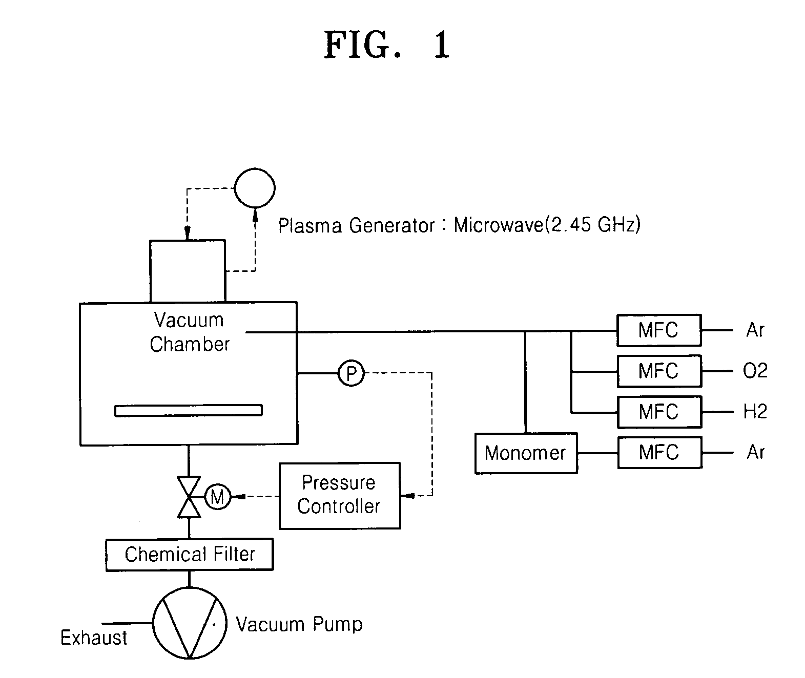
[0065] A plasma generating apparatus used for the plasma treatment is schematically illustrated in FIG. 1. The plasma treatment was performed at an argon flow rate of 30 cc / min, under pressure of 20 Pa, with plasma power of 100 W, for up to 30 minutes at 5-minute intervals. At this time, a plasma energy density was 1.12×10⁸ J / kg. Auto-fluorescence measurement conditions were the same as those in Example 1.

[0066] The experimental results are presented in Table 3 below. As shown in Table 3, the level of auto-fluorescence from the plastic substrates was increased with a linear increment of about 110 per one minute.

TABLE 3Plasma tre...


PUM

PropertyMeasurementUnit
Frequencyaaaaaaaaaa
Frequencyaaaaaaaaaa
Boiling pointaaaaaaaaaa

Abstract

Provided is a method of manufacturing a plastic substrate with lower auto-fluorescence and better specificity. The method includes: (a) preparing a plastic substrate having an Atomic Force Microscopic (AFM) surface roughness of Ra<3 nm or Rq<4 nm under the condition of 50 μm×50 μm or less; (b) treating the plastic substrate with plasma; and (c) treating the plastic substrate with a surface-modifying monomer. A plastic substrate manufactured by the method is also provided. The plastic substrate exhibits a remarkably low auto-fluorescence and thus better specificity for detection of target biomolecules, which enables the broad application of a plastic substrate, which can be easily designed to include a microfluidic structure relative to a glass substrate but has been limitedly used due to high auto-fluorescence, to microarrays, biochips, or well plates. Furthermore, the method of manufacturing the plastic substrate enables an enhancement in the surface specificity of the plastic substrate and easy adjustment of the surface characteristics of the plastic substrate.

Description

CROSS-REFERENCE TO RELATED PATENT APPLICATION [0001] This application claims priority from Korean Patent Application No. 10-2005-0096950, filed on Oct. 14, 2005, No. 10-2006-0013007, filed on Feb. 10, 2006, and No. 10-2006-0026044, filed on Mar. 22, 2006, in the Korean Intellectual Property Office, the disclosures of which are incorporated herein in their entireties by reference. [0002] 1. Field of the Invention [0003] The present invention relates to a method of manufacturing a plastic substrate with high specificity for detection of a target biomolecule, and a plastic substrate manufactured using the method. [0004] 2. Description of the Related Art [0005] With development of the biotechnology, a DNA sequence, a protein sequence, etc. which contain the genetic information of an organism have been revealed. Thus, development of biochips for sequence determination, disease diagnosis, etc. has been actively performed. Biochips are tools where a high-density microarray of probe biomole...

Claims


Application Information

Patent Timeline
IPC IPC(8): B05D3/00C08J7/18B32B27/36B32B27/38B32B27/32
CPCB01L2300/0822Y10T428/24355B29C59/14C08J7/123C08J7/18B01J2219/00527B01J2219/00605B01J2219/0061B01J2219/00635B01J2219/00659B01J2219/0072B01J2219/00722B01L3/508B01L2300/0819B01L2300/168Y10T428/31507Y10T428/31511Y10T428/31536Y10T428/31855Y10T428/31938
Inventor JUNG, GIHUNEKANG, JINSEOKKIM, HEE JUKWON, JI HYUNLEE, YOUNG MEESEO, YOUNG SOOKIM, IN SOO
Owner LG LIFE SCI
Why Eureka
Try Eureka