Method and System for Monitoring Computer Networks and Equipment

a computer network and equipment technology, applied in the field of computer network and equipment monitoring systems and methods, can solve the problems of equipment deterioration, equipment damage, and inability to tolerate excess heat, dust or humidity, and achieve the effect of simple addition or change of functionality

Inactive Publication Date: 2007-04-19
AMERICA POWER CONVERSION CORP
View PDF98 Cites 45 Cited by
  • Summary
  • Abstract
  • Description
  • Claims
  • Application Information

AI Technical Summary

Benefits of technology

[0026] A further technical advantage of the present invention is its ability to provide access and control through a global network such as the internet and the capability to process HTTP, HTML, MIME, and SNMP standards.
[0027] An even further technical advantage of the present invention is the ability to provide a video image of a room upon the occurrence of a pre-set condition, such as a door opening or whenever the website is addressed.
[0028] Still further, a technical advantage of the present invention is the ability to perform continuous computer network monitoring, to monitor the environmental conditions of a computer room, and to evaluate individual network components and automatically provide a report in the event of an out-of-limit condition.
[0029] A still further technical advantage provided by the present invention is the ability to communicate with personnel monitoring the system via the internet or an intranet.
[0030] An even further technical advantage of the present invention is the ability to report equipment or environmental conditions via the internet through a Web page, email or through a pager or a telephone call.
[0031] A still further a technical advantage of this invention is a downloadable memory function to make adding or changing functionality simple.

Problems solved by technology

Keeping track of numerous computers, along with associated bridges, routers, backup power supplies, etc., can be a formidable task.
While reliable, modern computer systems cannot tolerate excess heat, dust or humidity.
Heat can rapidly cause equipment deterioration.
Failure of CPU cooling fans can reduce equipment lifetime to days or hours.
A single high-speed LAN (local area network) failure can cause slow system response.
These and other such failures within the equipment in a server room occur routinely and can cause great disruption to a business.
However, these solutions are primarily targeted at high-end, very large systems such as those used by large corporations or institutions that have large budgets to support equipment monitoring.
Some of these systems only permit inspection of devices on a local basis.
However, all of these solutions are expensive to implement and complex and difficult to maintain and train personnel to use them.
As a result, small to medium companies having small to medium networks are left in the position of requiring a means to monitor and maintain their computer network equipment from failing while not having the resources to afford the high-priced solutions currently available.
Many firms cannot afford a high-end solution or simply do not have the time and resources to train their IT personnel to learn and use complex systems.
The reality, however, is that most IT managers have suffered some form of server room damage from excess heat or other physical phenomenon or simply just failure.
This is especially true for companies having multiple server rooms and that have concerns about routine access to each of these rooms.
Additionally, concerns exist with current solutions regarding the manpower intensiveness of these solutions.
Most network monitoring solutions can consume a full- or part-time employee.
The financial justification for these systems is, therefore, difficult because network equipment typically fails yearly, or on a disaster basis, and the cost of recovery is seen as less than that of maintaining a full-time employee to routinely monitor the equipment.
Also, current monitoring solutions do not provide for video imaging of remote server locations over a network.
A server room's environment requires monitoring because out of limit environmental variables can eventually affect the equipment in the room.
For example, high temperatures, humidity (for example, from water leaks), or lack of air flow can detrimentally affect the equipment.
While the expense of replacing server room components if they fail is great, currently existing monitoring solutions are not cost effective for smaller-sized companies to implement despite the potential costs of such losses.

Method used


Image

  • Method and System for Monitoring Computer Networks and Equipment
  • Method and System for Monitoring Computer Networks and Equipment
  • Method and System for Monitoring Computer Networks and Equipment

Examples


Embodiment Construction

[0059] Preferred embodiments of the present invention are illustrated in the FIGURES, like numerals being used to refer to like and corresponding parts of the various drawings.

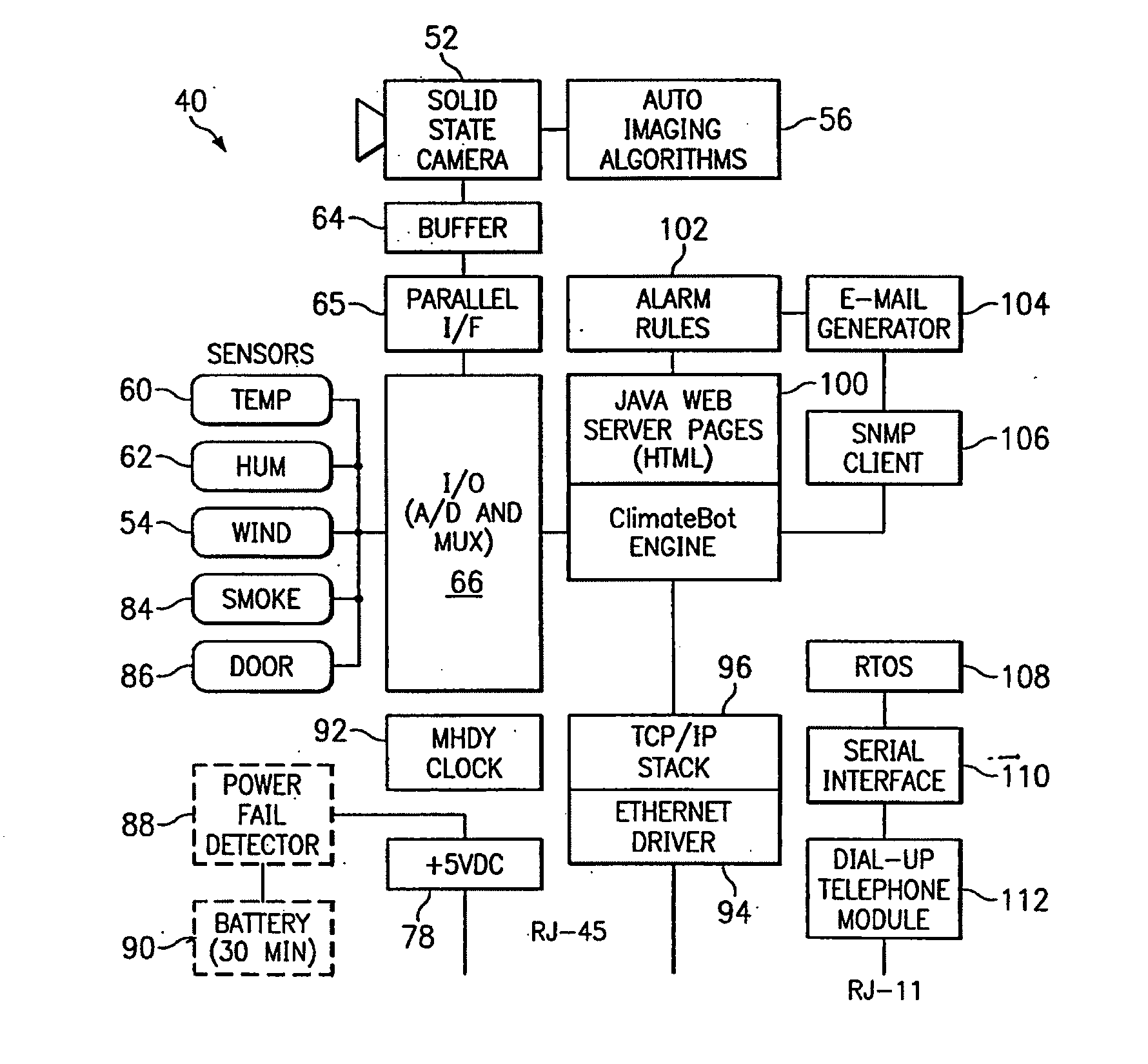
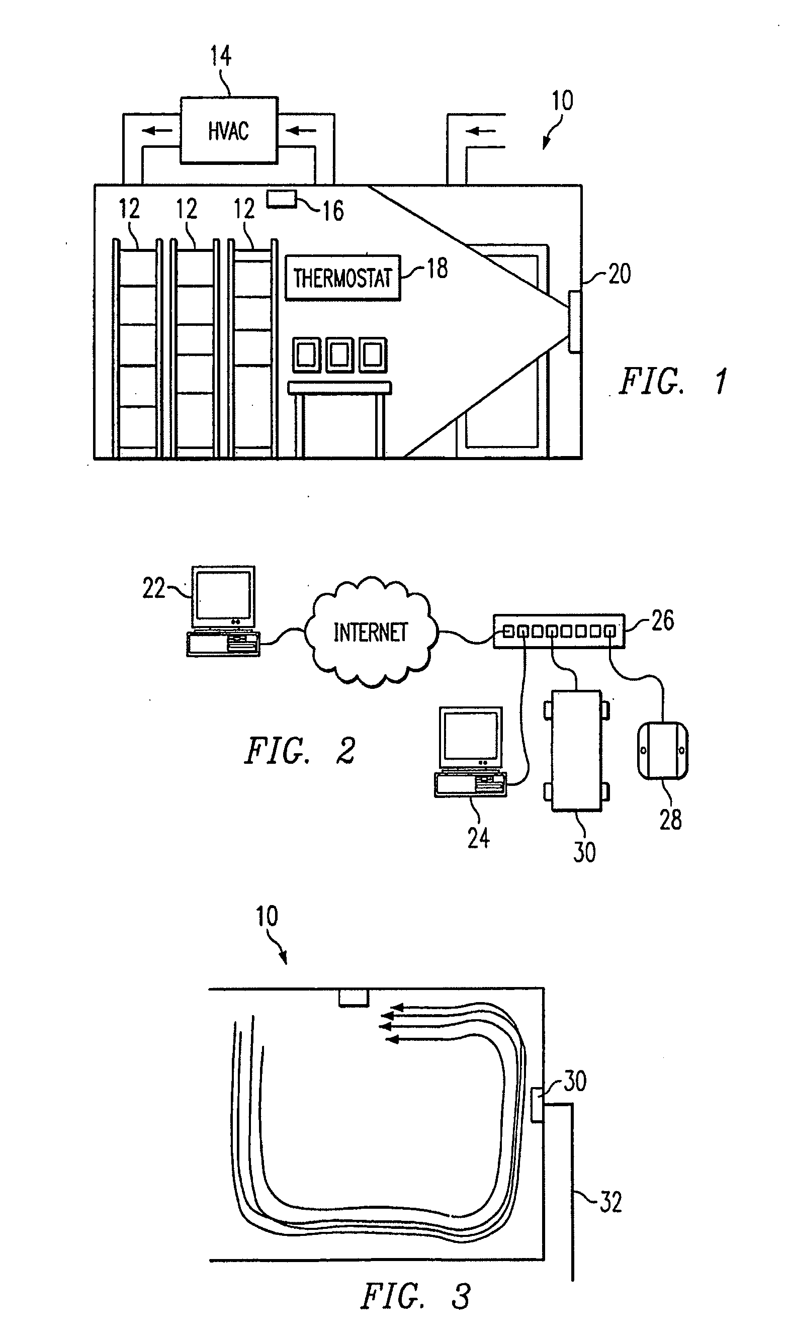
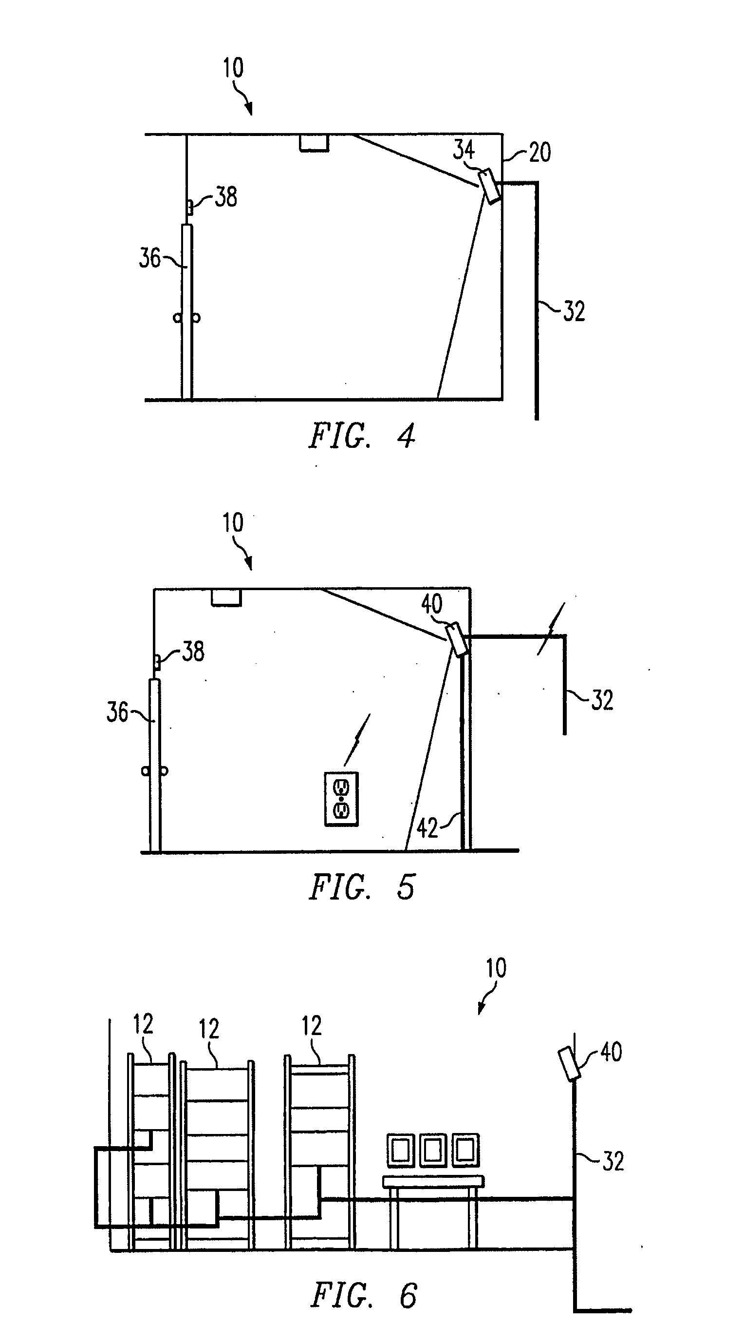
[0060] The method and system of the present invention can provide a simple, reliable, easy to manage and low-cost means for monitoring a network and the physical environment housing the network. Various embodiments of the present invention can provide one or all of physical environment monitoring, monitoring of individual component parts, video imaging of the physical space housing a server system, internet or Intranet connectivity and telephone-line notification. The method and system of the present invention can be implemented in data networks of very large companies with large network operation centers and deployed worldwide networks, to small companies with one internet server or a single computer room. In particular, the low cost, low maintenance, internet connectivity, and ease of use of the method and ...


PUM


Abstract

A system and method are disclosed for monitoring a space and its contents over a network. The system can include an embedded Java microprocessor to provide processing and network connectivity capability, and sensors to detect physical parameters associated with the space. The sensors can generate one or more sensor signals representative of the detected physical parameters. An analog-to-digital converter can convert the sensor signals to a digital format and can provide corresponding digital signals to the microprocessor. The system further includes instructions for processing the sensor signals and corresponding digital signals. An alarm signal can be generated when any of the physical parameters exceeds a corresponding threshold value. The system of the present invention can have at least one input / output port for communicating with the network and one or more memory modules for storing system data. The system of this invention can have a network-based interface for providing programming instructions to the microprocessor and for receiving monitoring status and alarm information from the system. The interface can be an HTML interface. A power source provides power to the system.

Description

RELATED APPLICATIONS [0001] This application is a continuation of prior U.S. application Ser. No. 10 / 775,899, filed Feb. 10, 2004, which is a continuation of prior U.S. application Ser. No. 09 / 429,504, filed Oct. 27, 1999, both of which are incorporated by reference herein in their entirety.TECHNICAL FIELD OF THE INVENTION [0002] The present invention relates generally to computer network and equipment monitoring systems and methods and, more particularly, to computer network monitoring systems that can be accessed locally or remotely. Even more particularly, the present invention relates to a computer network and equipment monitoring system that can provide real-time status of environmental conditions, alarm functions, and real-time video imaging of a space or equipment being monitored over a global network, such as the internet. BACKGROUND OF THE INVENTION [0003] Data traffic on networks, particularly on the internet, has increased dramatically over the past several years, and thi...

Claims


Application Information

Patent Timeline
Patent Type & Authority Applications(United States)
IPC IPC(8): G06F15/173G05B15/00G06F15/16H04H60/31H04L12/24H04L12/26H04L12/28H04L12/44H04L29/08H04N7/16H04N7/173H04N17/00H04N17/02
CPCH04L12/2803H04L12/2825H04L12/44H04L43/045H04L43/065H04L43/0817H04L43/10H04L43/12H04L43/16H04L2012/2841H04L2012/2845H04L67/025H04L67/12H04L67/02H04L69/329
Inventor FOWLER, JOHN J.CULLEN, GERARD L.
Owner AMERICA POWER CONVERSION CORP
Why Eureka
Try Eureka