Emergency brake device for elevator

a technology for emergency brakes and elevators, which is applied to elevators, vehicle components, braking systems, etc., can solve the problems of increasing the speed of the car during this time lag, the mechanical engagement of the inserted braking member or the clamp is not provided, and the structure is complex

Inactive Publication Date: 2007-04-26
MITSUBISHI ELECTRIC CORP
View PDF5 Cites 6 Cited by
  • Summary
  • Abstract
  • Description
  • Claims
  • Application Information

AI Technical Summary

Problems solved by technology

However, each of the conventional emergency brake devices as described above requires a space dedicated for the provision of the brake device and is rather complex in structure.
Further, with the emergency brake device in which the braking bolt is inserted between the spokes, there is a time lag between the engagement of the braking bolt with the spokes and the generation of a braking force, so there is a problem in that the speed of the car increases duri

Method used


Image

  • Emergency brake device for elevator
  • Emergency brake device for elevator
  • Emergency brake device for elevator

Examples


embodiment 1

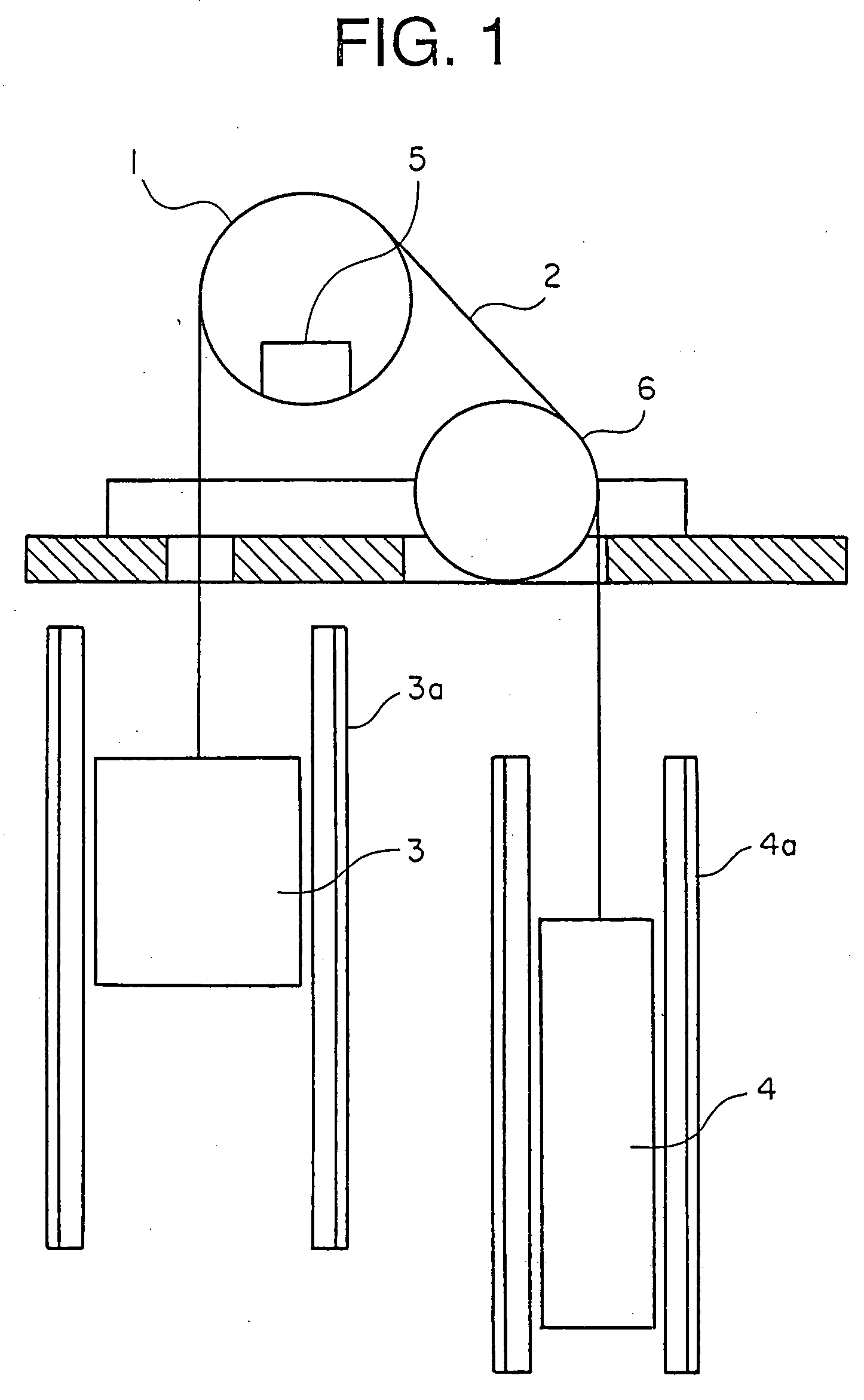
[0015]FIG. 1 is a view showing the construction of a traction type elevator apparatus equipped with an emergency brake device for an elevator according to the present invention. In the traction type elevator apparatus, a car 3 and a counterweight 4, which are respectively raised and lowered along guide rails 3a, 4a within a hoistway, are connected with each other by a wire rope 2 and the wire rope 2 is wound around a hoisting machine sheave 1 and a deflector sheave 6 in the manner of a pulley, the car 3 being driven by utilizing the friction force between the wire rope 2 and the hoisting machine sheave 1. An emergency brake 5 according to the present invention is provided, for example, inside the sheave 1.

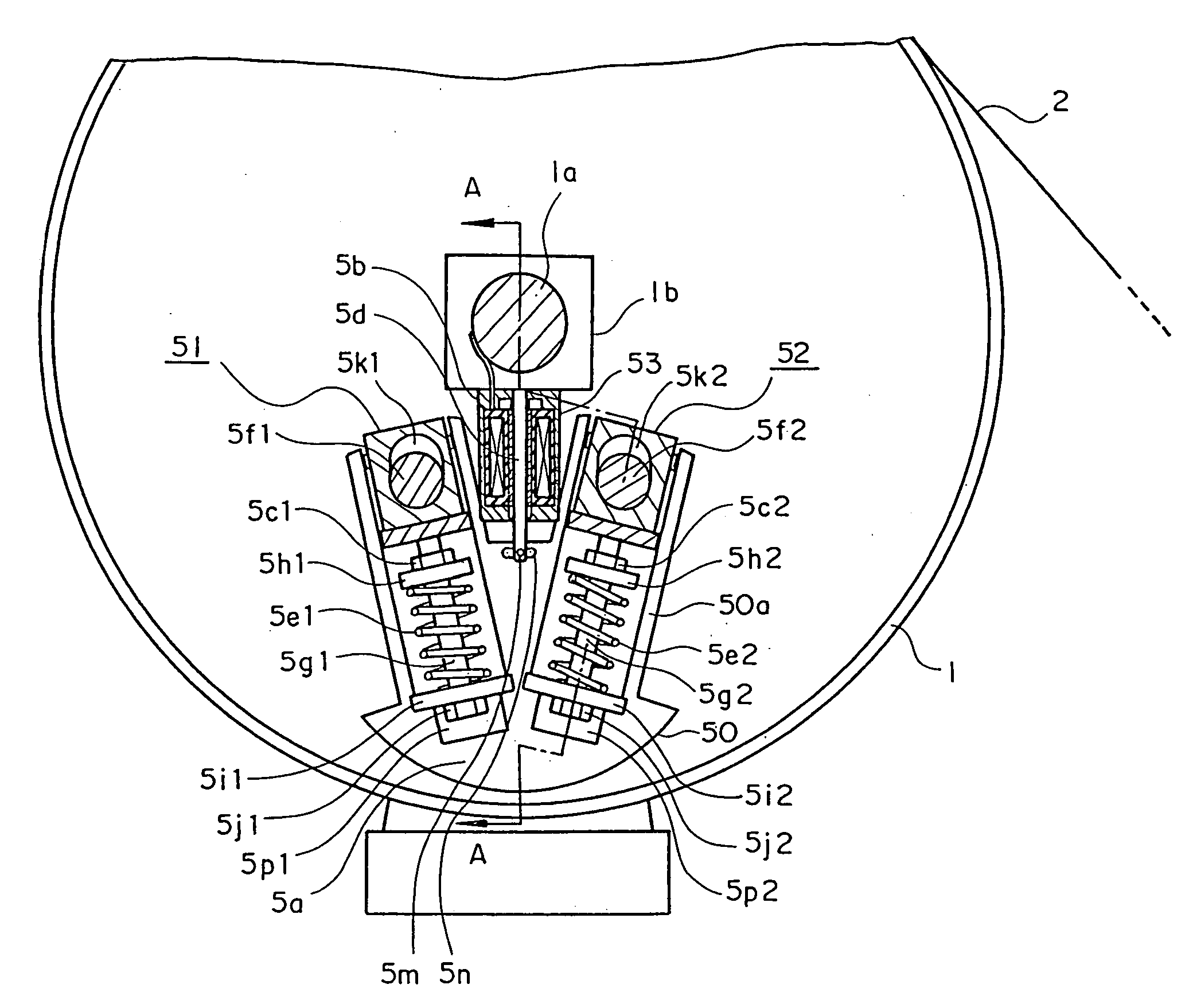
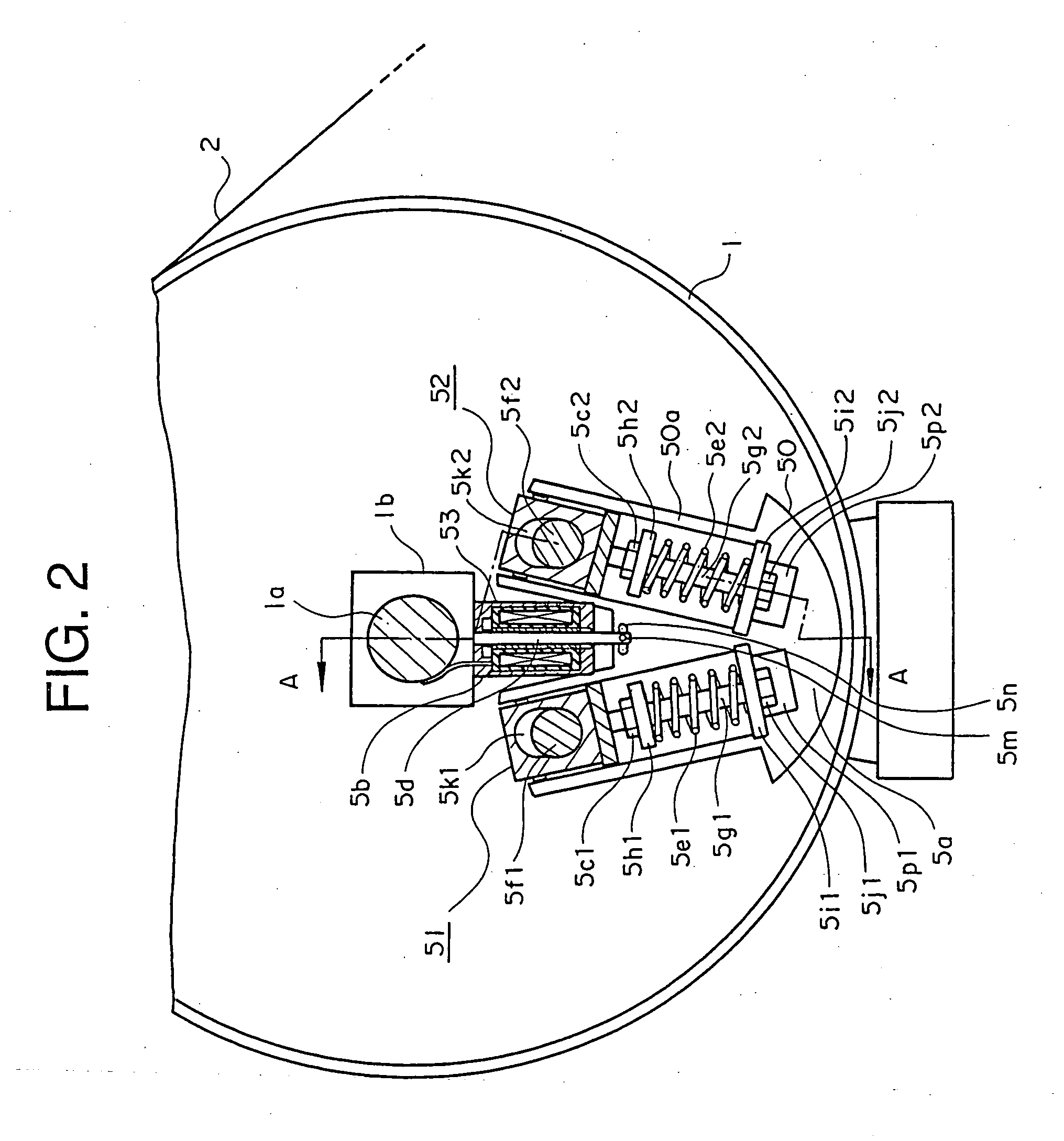
[0016]FIG. 2 through FIG. 4 are perspective views, partly in section, showing an example of the emergency brake 5 provided inside the sheave 1. FIG. 2 and FIG. 3 are views basically along the line B-B of FIG. 4, respectively showing the emergency brake 5 when in operation and when...


PUM


Abstract

An emergency brake device for an elevator includes a brake shoe portion provided inside a sheave 1 or deflector sheave of an elevator and having a brake shoe 5a at a lower end of the brake shoe portion, the brake shoe generating a braking force due to friction upon abutting an inner wall of an outer peripheral frame of the sheave or deflector sheave at a time of braking, the brake shoe portion having built therein spring mechanisms 51, 52 provided between the brake shoe and king pins 5f1, 5f2, which are offset in a rotation direction of the sheave or deflector sheave with respect to a centerline passing through a rotation shaft of the sheave or deflector sheave and are fixed on a bearing 1b side of the rotation shaft, the spring mechanisms each absorbing a force generated between the brake shoe and the king pin due to the braking force and being connected to the king pin at one end.

Description

TECHNICAL FIELD [0001] The present invention relates to an emergency brake device for an elevator. BACKGROUND ART [0002] Conventionally, there are emergency brake devices in which an emergency stop or a speed governor is disposed on the counterweight side or which are provided with a rope brake that directly grips a main rope for cases where a car moves upwards at a speed higher than a rated speed due to a failure or accident in an elevator, due to an unbalance in weight between the elevator car and a counterweight, or the like. [0003] Further, JP 5-193860 A discloses an emergency brake device having a braking bolt inserted between the spokes mounted to the shaft of the drive sheave. [0004] Further, JP 6-199483 A discloses a brake device that stops a deflector sheave by pushing a wedge-like braking member between the sheave or the deflector sheave and the pressing member. [0005] Further, JP 2002-241064 A discloses an emergency stop device in which wedge-like clamps are inserted on b...

Claims


Application Information

Patent Timeline
IPC IPC(8): B66B5/00B66B5/02B66B5/16
CPCB66B5/02
Inventor ITO, KAZUMASA
Owner MITSUBISHI ELECTRIC CORP
Why Eureka
Try Eureka