Emergency power shutdown management system

a management system and power shutdown technology, applied in the field of emergency power shutdown management system, can solve the problems of inability to easily defeat these systems, no easy way to defeat these systems, and emergency power off controls installed in this fashion are subject to some troubling ongoing operational problems, so as to achieve effective consolidation, control, and monitor

Active Publication Date: 2007-04-26
FIKE CORP
View PDF1 Cites 20 Cited by
  • Summary
  • Abstract
  • Description
  • Claims
  • Application Information

AI Technical Summary

Benefits of technology

[0007] The present invention solves the above-described problems and provides a distinct advance in the art of emergency power shutdown management systems. More particularly, the present invention provides a system that more effectively consolidates, controls, and monitors the power off circuits for a room or other zone.

Problems solved by technology

Unfortunately most emergency power off controls are afterthoughts.
Moreover, these systems are typically undocumented—no wiring diagrams, location of devices, and intended sequence of operation.
Additionally, there are typically no easy ways to defeat these systems during routine maintenance.
Emergency power off controls installed in this fashion are also subject to some troubling ongoing operational issues.
For example, such systems can be unreliable in that wires can be disconnected or shunt-trip power circuits turned off rendering the controls useless with no trouble alarm or notification to users.
Similarly, since there are no simple ways to disable these controls, accidental activation and thus accidental equipment shutdown can and does occur.
Due to lack of documentation, changes or troubleshooting is cumbersome and costly.

Method used


Image

  • Emergency power shutdown management system
  • Emergency power shutdown management system
  • Emergency power shutdown management system

Examples


Embodiment Construction

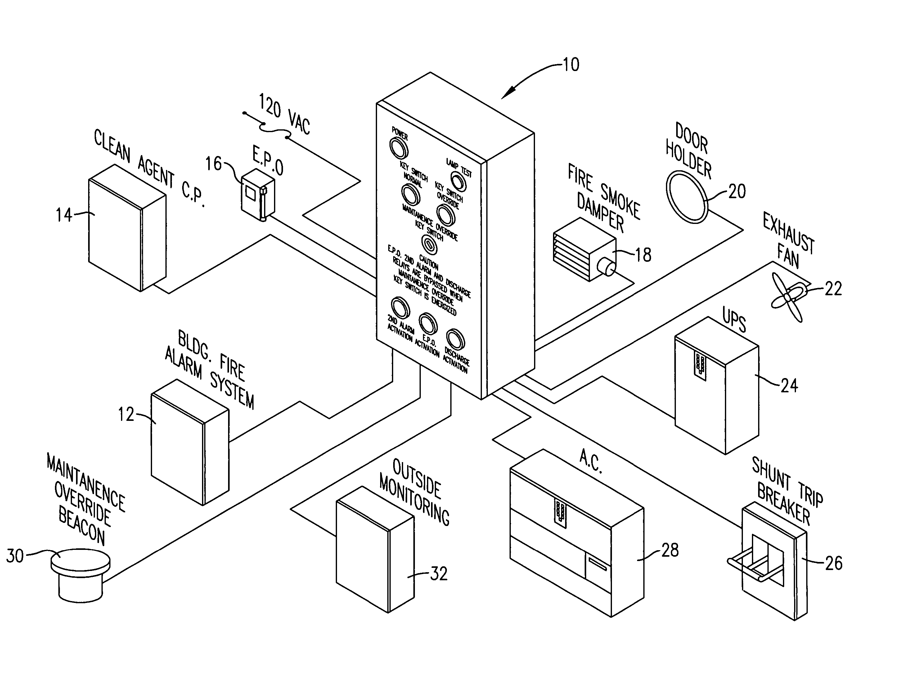
[0018] An EPSMS 10 constructed in accordance with a preferred embodiment of the present invention is shown in the drawing figures. As illustrated in FIG. 3, the EPSMS 10 maybe coupled with various input signal sources, controlled devices, and monitoring devices for consolidating, controlling, and monitoring the shut-down of the controlled devices. For example, the EPSMS may receive input signals from a fire control panel 12, a clean agent control panel 14, and an emergency power off (EPO) switch or button 16. The controlled devices may include a fire / smoke damper 18, one or more electrically operated door holders 20, an exhaust fan 22, an uninterruptible power supply (UPS) 24, equipment connected to one or more shunt trip breakers 26, and an air conditioning unit 28. The monitoring devices may include a maintenance override beacon 30 and one or more remote or outside monitoring stations 32. These are just some of the examples of the devices which can be coupled with the EPSMS, as th...


PUM


Abstract

An emergency power shutdown management system (EPSMS) comprises a programmable logic controller (PLC), relays coupled to the outputs of the PLC for shutting down electrically operated equipment, and indicators for indicating the status of the EPSMS and the controlled equipment. The PLC receives input signals from a fire control panel including a 2nd alarm signal which is generated after the fire control panel has detected smoke, fire or an explosion with two or more detectors and a system discharge signal which is generated when the fire control panel triggers fire sprinklers or the release of other fire or explosion suppression agents. The PLC also receives an emergency power off (EPO) signal from an EPO switch which is activated to immediately shut down all electrically operated equipment and power distribution units in a protected area. The indicators include a 2nd alarm indicator for indicating a 2nd alarm activation; a system discharge indicator for indicating a discharge of fire or explosion suppression agents; and an emergency power off indicator for indicating an emergency power off situation. The relays include 2nd alarm equipment relays coupled with a first set of equipment; system discharge relays coupled with a second set of equipment; and shunt trip relays coupled with a third set of equipment. All of the components of the EPSMS are housed within a single cabinet for consolidating the control and alert functions of the EPSMS in a single location.

Description

BACKGROUND OF THE INVENTION [0001] 1. Field of the Invention [0002] The present invention relates to an emergency power shutdown management system. More particularly, the invention relates to such a system that consolidates, controls, and monitors the power off circuits for a room or other zone protected by a fire or explosion protection system. [0003] 2. Description of the Prior Art [0004] Many buildings, factories, and other facilities include rooms or other zones protected by fire and / or explosion suppression equipment. Before and during operation of such suppression equipment, it is necessary to control and shut down certain electrically operated equipment. For example, before discharge of a fire or explosion suppression agent into a room, it is desirable to first shut down air handling units, exhaust fans, etc. to prevent interference with the dispersion of the suppression agent. It is also necessary to shut off all power and power distribution units to protect firefighters and...

Claims


Application Information

Patent Timeline
Patent Type & Authority Applications(United States)
IPC IPC(8): G08B29/00G08B21/00
CPCH02H5/00
Inventor ROARK, CHRISTOPHER DEANZABOSKI, JAMES B.
Owner FIKE CORP
Why Eureka
Try Eureka