Rear projection screen, and rear projection system using the screen

a technology of rear projection and projection screen, which is applied in the direction of projectors, optics, instruments, etc., can solve the problems of reduced image intensity, difficult to manufacture, and serious limitations of artifacts, and achieves enhanced image contrast, high transmission efficiency, and high contrast

Inactive Publication Date: 2007-04-26
MICROSHARP CORP LTD
View PDF20 Cites 105 Cited by
  • Summary
  • Abstract
  • Description
  • Claims
  • Application Information

AI Technical Summary

Benefits of technology

[0013] Advantageously, the rear projection screen may achieve high transmission efficiency whilst optionally providing high contrast across the screen for the obliquely incident light beam. The back face of the screen comprises a prismatic structure which may incorporate one or more curved facets in the prismatic unit which is repeated across the screen. If employed, the one or more curved facet of a lenticular prism acts as a light concentrator to focus light in order to enhance the contrast of a displayed image.
[0015] The rear projection screen may be illuminated by an image engine source, the light being incident on the screen at an angle of incidence of at least =b 45 degrees. The screen microstructure is such that it facilitates the manufacturing of the tooling required for mass production, and is capable of accommodating minor misalignment of the screen during TV system assembly.
[0028] Advantageously, the third section is coated to enhance the total internal reflection effect.
[0035] Preferably, the second section is coated to enhance the total internal reflection effect.
[0039] According to a further aspect of the invention, there is provided a rear projection video system incorporating an optical panel in accordance with the invention. Preferably, the rear projection video system further comprises at least one light generation system. Advantageously, the light generation system includes: a single light source or a plurality of light sources; and a Digital Processing unit for reduction of keystone-type distortion of the image. Alternatively, the light generation system includes: a single light source or a plurality of light sources; and an anamorphic optical element for reducing keystone-type distortion of the image. Alternatively still, the light generation system includes: a single light source or a plurality of light sources; and a hybrid optical / digital element or elements for reduction of keystone-type distortion of the image.

Problems solved by technology

However the reduction of the intensity of viewed images due to moiré patterns and ghost images which tend to result from the use of the Fresnel lens are important issues: such artifacts can represent a serious limitation, as reported in U.S. Pat. No. 6,249,376.
The width ratio of the refraction and the total internal reflection parts of the composite refraction / reflection element is changed gradually in accordance with the variation in the incidence angle across the film: such a structure is evidently complex to manufacture.
Furthermore, any gain in intensity uniformity of the display is at the cost of optical efficiency, due to the locally substantial off-normal angle of incidence of the light entering the composite reflection / refraction element.
This prevents realization of a very slim profile TV system.

Method used


Image

  • Rear projection screen, and rear projection system using the screen
  • Rear projection screen, and rear projection system using the screen
  • Rear projection screen, and rear projection system using the screen

Examples


Embodiment Construction

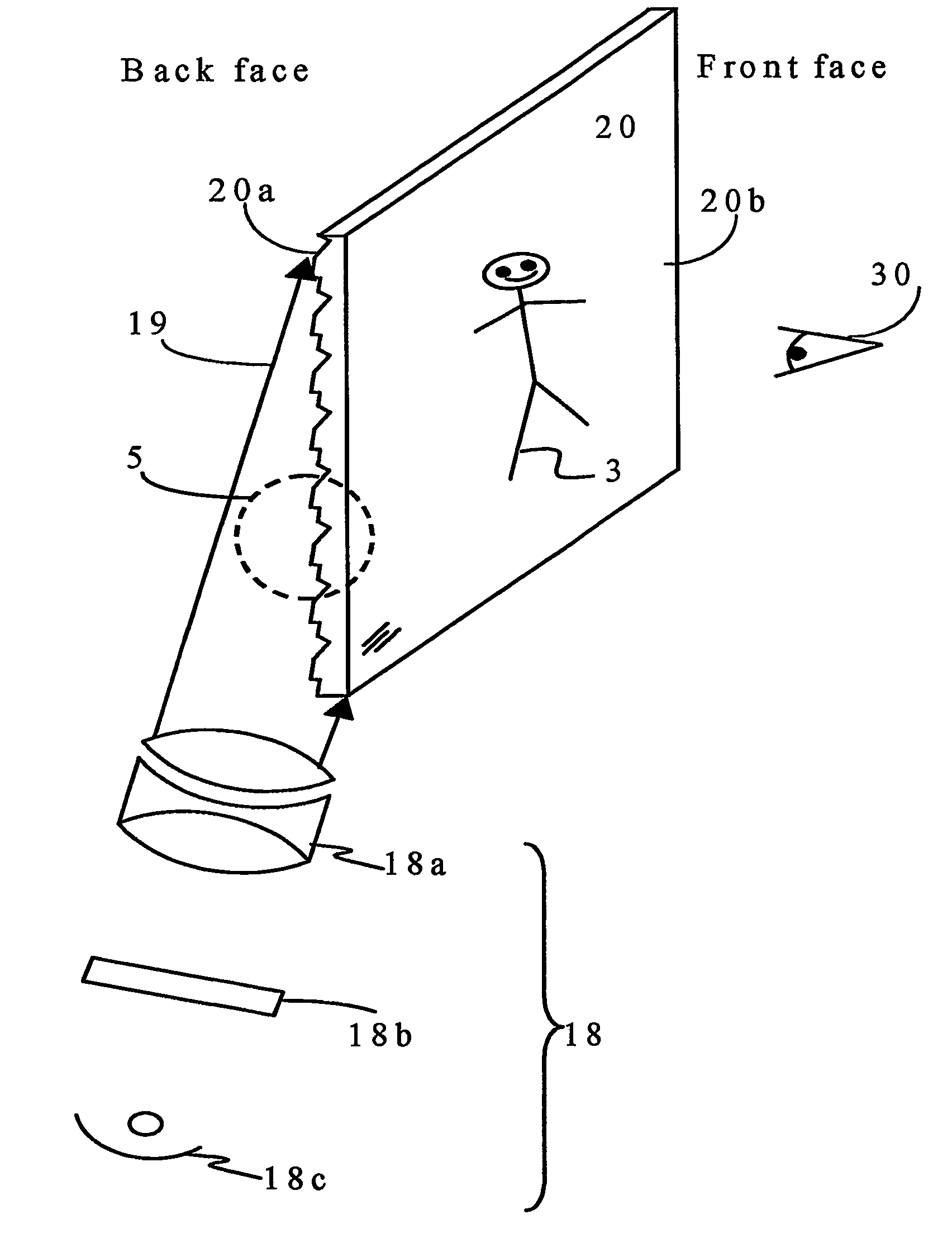
[0062] Referring to FIG. 3, there is shown a schematic view illustrating an optical panel. 20 in a rear projection video system in accordance with an exemplary embodiment of the invention.

[0063] The system may be housed in a slim, compact, cabinet with the optical panel 20: the housing will include all working components. In the embodiment shown in FIG. 3, the optical panel 20 is placed in combination with a projector 18 suitably designed for projecting a video image 3 onto the optical panel for direct viewing by an observer 30 facing the optical panel.

[0064] The system allows the dimensions of the panel 20 to be scaled for any desired application, from a large screen suitable for viewing by the crowd at a sports stadium to a small screen suitable for a portable display such as one on a mobile phone.

[0065] In the arrangement shown, the projector 18 comprises a light source 18c, a light modulator 18b, and imaging optics 18a which direct light, from light source 18c, after modulati...


PUM


Abstract

A rear projection screen (20) and a rear projection video system using the screen are disclosed. A rear face (20a) of the screen (20) has a structured surface comprising a plurality of light-redirecting elements having transparent planar and / or curved facets (10-13b); each element comprises a facet (10) for transmitting incident light (19), a facet (12) for internally reflecting the transmitted light, at least one facet (11) intermediate and adjoining the facets (10, 12), and a further section (13a, 13b, 52) for separating the facets from those of adjacent elements. Internal angles at the junctions between the first and intermediate, and the intermediate and second, facets (10 &11, 11 &12) are at least 90° and no greater than 180°. The front face (20b) of the screen (20) may comprise black stripes (15, 53) and lenticular lenses (14, 40a, 59) to enhance the contrast of the screen. Improved tolerances in manufacturing of the tooling for the screen (20) and against minor component misalignments during system assembly are hereby provided, as are improvements to the robustness of the screen microstructure.

Description

FIELD OF THE INVENTION [0001] This invention relates to a rear projection screen for a rear projection display, such as a rear projection television system. BACKGROUND OF THE INVENTION [0002] Conventional rear projection systems include an image engine source, optics to enlarge and to direct the image light and a transmission screen that is intended to diffuse the image towards a viewing space. [0003] The depth dimension of rear projection systems is traditionally reduced by a set of mirrors that are designed and confined in a compact way to produce a relatively large, contiguous image in a relatively small cabinet. Diverse configurations have been disclosed that make use with some efficiency of the space within the rear projection cabinet. U.S. Pat. No. 3,947,104 discloses a compact imaging apparatus which projects an image upwards using a series of two folding mirrors. U.S. Pat. No. 6,388,810 discloses a rear projection mirror arrangement that includes a curved shape mirror to pro...

Claims


Application Information

Patent Timeline
Patent Type & Authority Applications(United States)
IPC IPC(8): G03B21/56G03B21/62
CPCG03B21/62
Inventor MEZOUARI, SAMIRO'NEIL, ANNA TAYLORLEE, YONGMINKHANDAKER, IMAN IBRAHIM
Owner MICROSHARP CORP LTD
Why Eureka
Try Eureka