Flat light-emitting apparatus

a light-emitting apparatus and flat technology, applied in lighting and heating apparatus, discharge tube luminescnet screens, instruments, etc., can solve the problems of low color saturation and low light efficiency depending on the different light sources

Active Publication Date: 2007-04-26
EPISTAR CORP
View PDF15 Cites 11 Cited by
  • Summary
  • Abstract
  • Description
  • Claims
  • Application Information

AI Technical Summary

Problems solved by technology

As to those typical light-emitting elements, there are several disadvantages such as low color saturation and low light efficiency depending on the different light sources and the combinations.

Method used


Image

  • Flat light-emitting apparatus
  • Flat light-emitting apparatus

Examples


Embodiment Construction

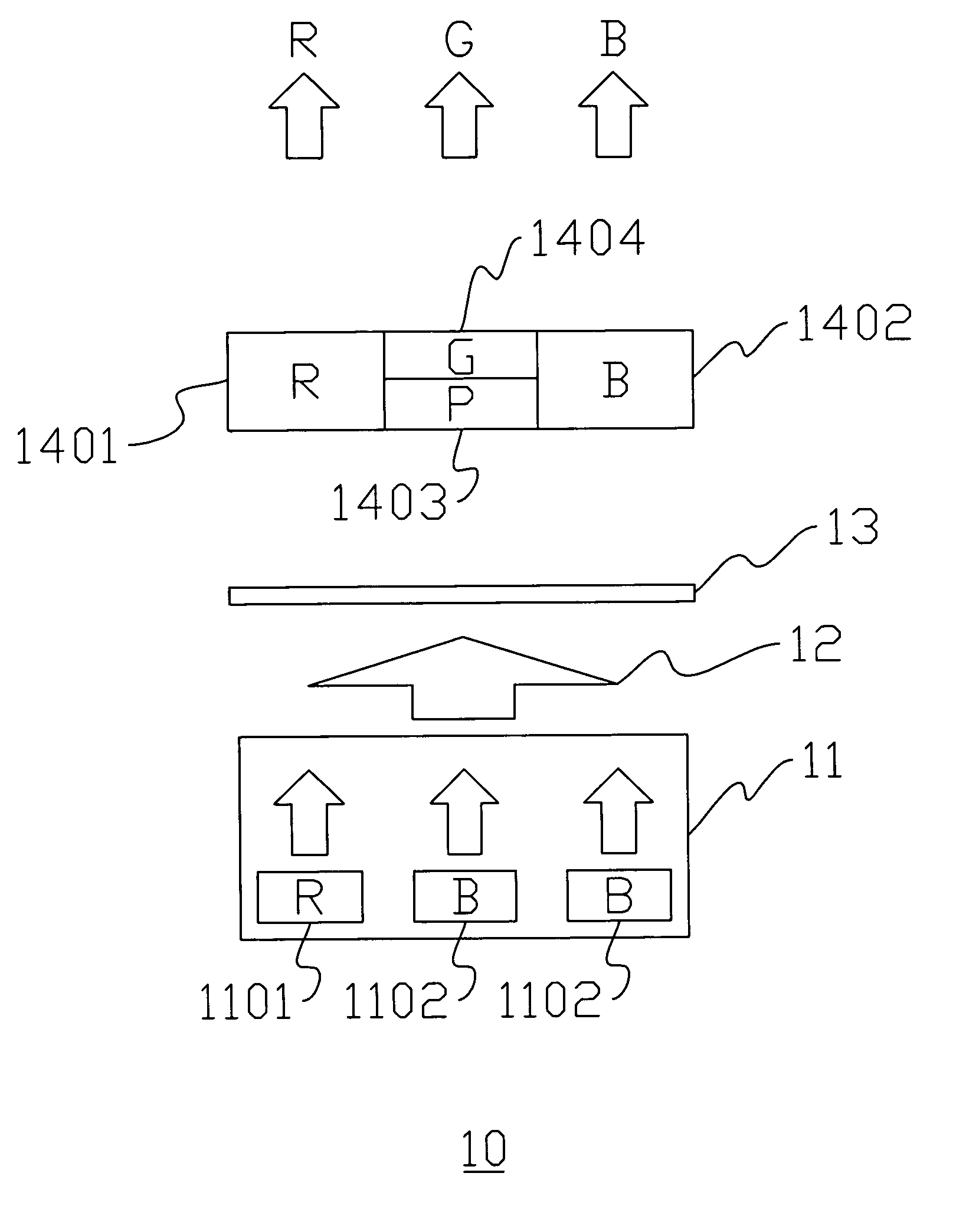
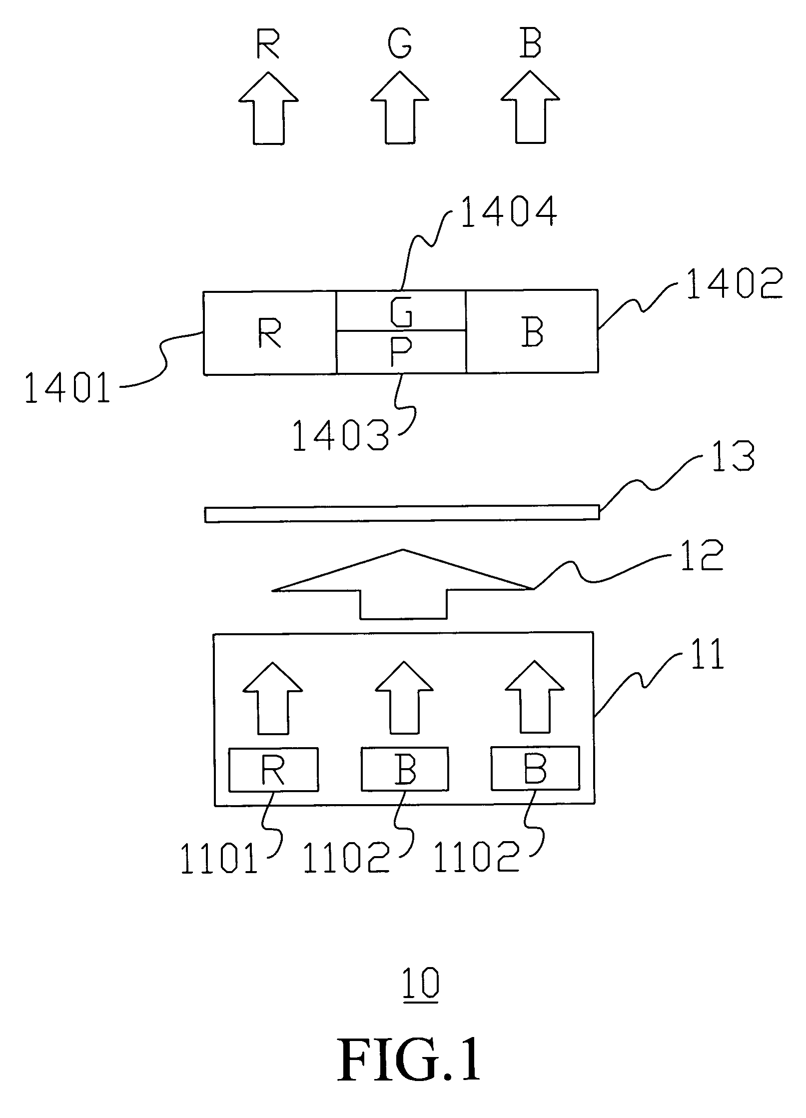
[0010] Referring to the FIG. 1, an embodiment of the present invention will be described below. A flat light-emitting apparatus 10 comprises an LCD module (not shown) with a liquid crystal layer 13 and a backlight module (not shown) with a light-emitting element 11. Typically, there are two types of the backlight modules. One is the bottom lighting type, and the other is the edge lighting type. The bottom lighting type backlight module is located below the LCD module and is composed of a diffuser and several optical films. The edge lighting type backlight module is located at one side of the LCD module and is composed of a diffuser, several optical films, and a light guide plate for leading a light emitted form the light-emitting element 11 to the LCD module.

[0011] The light-emitting element 11 includes a red light-emitting component 1101 with a wavelength substantially not less than 600 nm, preferably between 610 nm˜710 nm, and a blue light-emitting component 1102 with a wavelengt...


PUM


Abstract

A flat light-emitting apparatus includes a light-emitting element for radiating visible light consisting of a first-wavelength light with a wavelength substantially not less than 600 nm and a second-wavelength light with a wavelength substantially not greater than 480 nm, a wavelength conversion material for generating a third-wavelength light when irradiated by the second-wavelength light, a first color filter for the passing of the first-wavelength light, a second color filter for the passing of the second-wavelength light, and a third color filter for the passing of the third-wavelength light.

Description

TECHNICAL FIELD [0001] This invention relates to a flat light-emitting apparatus, and more particularly to a flat panel display capable of generating green light by making blue light pass through a phosphor and a green color filter. REFERENCE TO RELATED APPLICATION [0002] This application claims the right of priority based on TW application Ser. No. 094137515, filed “Oct. 26, 2005”, entitled Flat Light-emitting Apparatus and the contents of which are incorporated herein by reference. BACKGROUND OF THE INVENTION [0003] TFT Liquid Crystal Displays are widely applied to different products such as handset apparatus, notebooks, monitors and flat TVs on the strength of their characteristics including thinner, lighter in weight, and lower power consumption in comparison with traditional CRTs (Cathode Ray Tubes). [0004] A TFT Liquid Crystal Display comprises a backlight module and an LCD module. The light emitted from the backlight module passes through the LCD module and is converted into ...

Claims


Application Information

Patent Timeline
Patent Type & Authority Applications(United States)
IPC IPC(8): F21V9/00
CPCG02F1/133617G02F1/1335
Inventor HSIEH, MIN-HSUNWANG, CHIEN-WUAN
Owner EPISTAR CORP
Why Eureka
Try Eureka