Reactor containment vessel and boiling water reactor power plant

a technology for nuclear reactors and containment vessels, which is applied in nuclear engineering problems, nuclear elements, greenhouse gas reduction, etc., can solve the problems of not being able to positively function, the reactor building surrounding the primary reactor containment vessel is not pressure resistant and cannot be equipped with an active safety system by design, and the soundness of the reactor containment vessel of conventional active safety bwrs can be threatened

Active Publication Date: 2007-04-26
KK TOSHIBA
View PDF5 Cites 83 Cited by
  • Summary
  • Abstract
  • Description
  • Claims
  • Application Information

AI Technical Summary

Problems solved by technology

The soundness of the reactor containment vessels of conventional active-safety BWRs can be threatened when a severe accident is considered to take place to go beyond the design basis.
The reactor building surrounding the primary reactor containment vessel is not pressure resistant and is not expected to positively function as an outer containment vessel of a double containment structure by design if the soundness of the primary reactor containment vessel were damaged.
On the other hand, conventional passive-safety BWRs are not equipped with an active-safety system by design.
Although the system cost of the passive-safety system is low, the pressure in the inside of the primary reactor containment vessel could increase once an accident occurred to damage the reactor core, because of non-existence of counter measure such as provision of vents and the large amount of hydrogen generated in the reactor core.
Additionally, the primary reactor containment vessel could be damaged by hydrogen detonation when an accident occurred because hydrogen would be discharged into the equipment room.
When contaminated with radioactivity or if the internal atmosphere of a lower equipment room replaced by hydrogen and an accident occurred, it would be difficult for operators to enter the equipment room for restoration activities.
However, the addition of such a secondary reactor containment vessel would be costly and cumbersome.

Method used


Image

  • Reactor containment vessel and boiling water reactor power plant
  • Reactor containment vessel and boiling water reactor power plant
  • Reactor containment vessel and boiling water reactor power plant

Examples


first embodiment

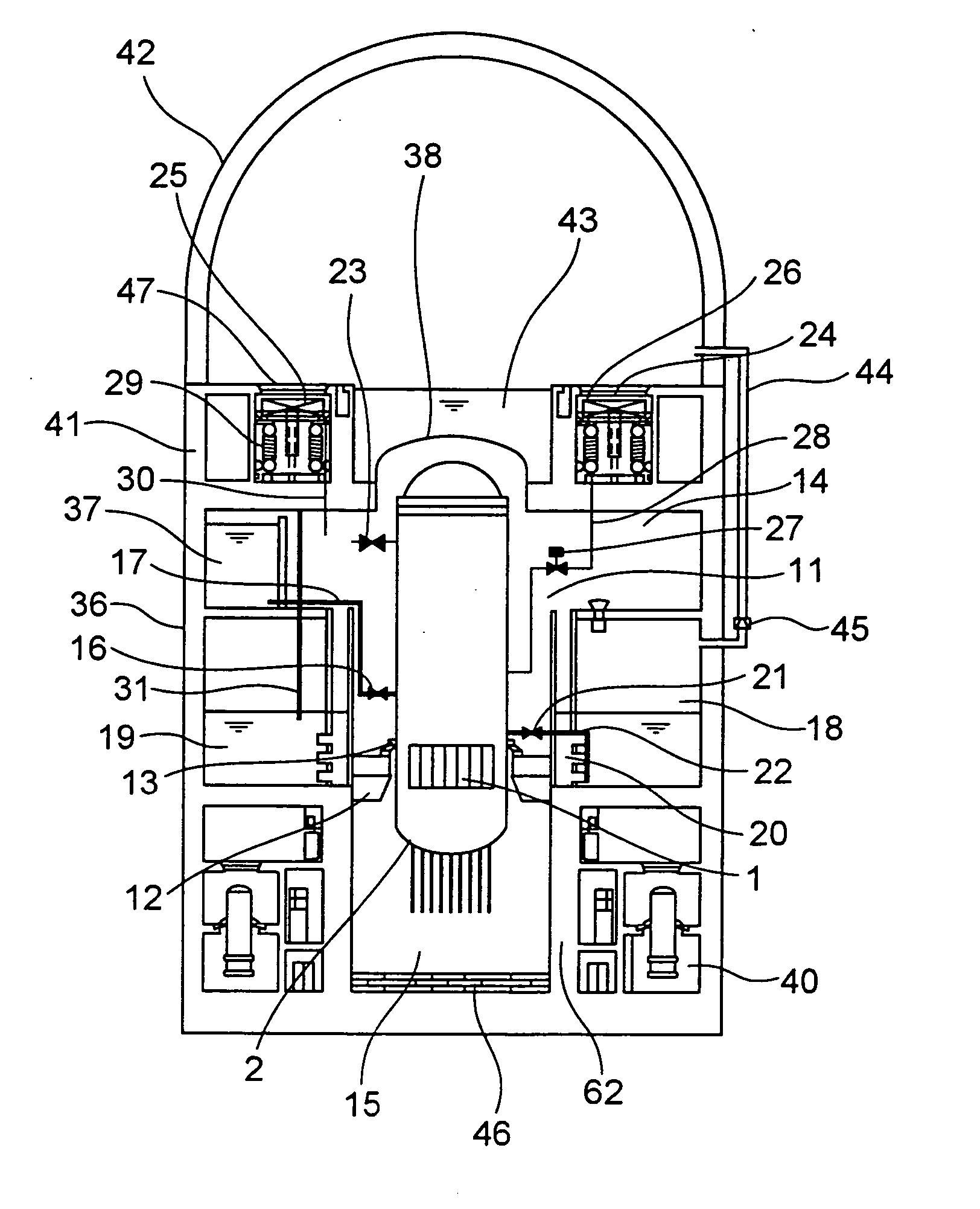
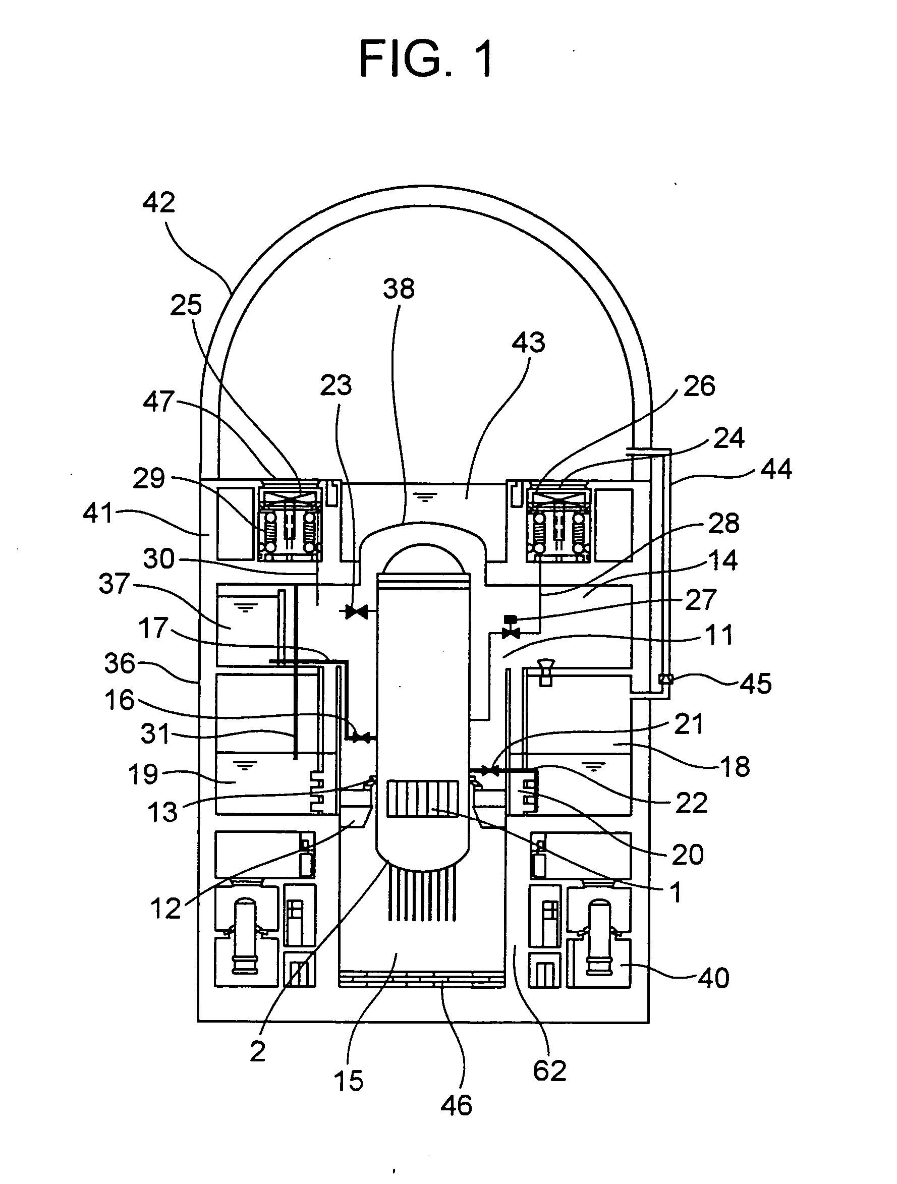
[0026] a reactor containment vessel (to be referred to simply as containment vessel hereinafter) according to the present invention will be described by referring to FIG. 1. As shown in FIG. 1, a reactor pressure vessel (RPV) 2 that contains a core 1 is arranged in the inside of a dry well 11 and rigidly secured in position by means of a reactor pressure vessel support 12 by way of areactor pressure vessel skirt 13. The space above the reactor pressure vessel support 12 in the dry well 11 is referred to as upper dry well 14, whereas the space below the reactor pressure vessel support 12 in the dry well 11 is referred to as lower dry well 15.

[0027] A core catcher 46 made of thermally resistant material is arranged on the floor of the lower dry well 15. The floor surface of the lower dry well 15 is highly reinforced so as to make it particularly resistant against leakage of and corrosion by radioactive substances. The part of the wall surface of the lower dry well 15 that supports the...

second embodiment

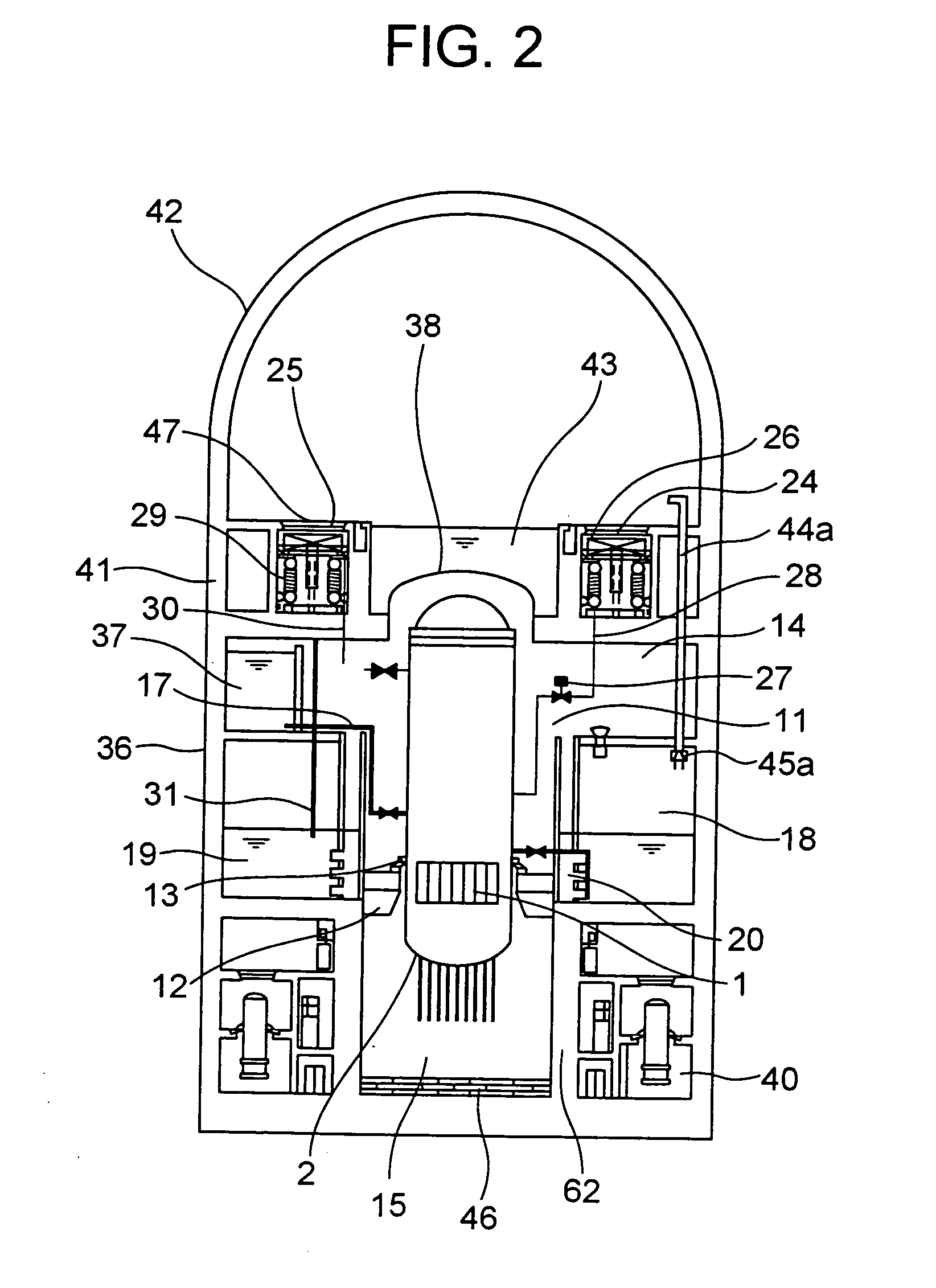
[0059] Now, the containment vessel according to the present invention will be described by referring to FIG. 2. In this embodiment, the gas-phase vent pipe 44a is not arranged outside the containment vessel 41, but it is arranged through the dry well 11 so as to connect the wet well 18 and the upper secondary containment vessel 42. The isolation and connection switching system 45a is arranged in the gas-phase part of the wet well 18. With this arrangement, the gas-phase vent pipe 44a does not extend to the outside of the containment vessel 41, so that it is possible to avoid radioactive substances from leaking into the environment through the gas-phase vent pipe 44a even if an accident occurs.

third embodiment

[0060] Now, the containment vessel according to the present invention will be described by referring to FIG. 3. In this embodiment, the upper secondary containment vessel 42 and the primary containment vessel 36 are integrally formed as a single structure of the containment vessel 41. Additionally, the gas-phase vent pipe 44b is embedded in the wall of the containment vessel 41.

[0061] With this arrangement of the embodiment, the containment vessel 41 is realized as an integrated single structure to provide an advantage of an enhanced strength. As the gas-phase vent pipe 44b is embedded in the wall, the overall structure can be designed very compact. The maintenance of the isolation and connection switching system 45b can be conducted easily because it is located in the gas-phase part. Alternatively, the isolation and connection switching system 45b may be placed in an opening space that is formed in the wall.


PUM


Abstract

A containment vessel includes a primary containment vessel containing a reactor pressure vessel, an upper secondary containment vessel arranged above the primary containment vessel, and a gas-phase vent pipe linking the primary containment vessel and the upper secondary containment vessel by way of an isolation and connection switching system. The gas-phase vent pipe may be arranged either inside or outside the primary containment vessel and the upper secondary containment vessel. Alternatively, it may be embedded in the wall. An igniter may be arranged in the upper secondary containment vessel. The air in the upper secondary containment vessel may be replaced by nitrogen. A gravity-driven flooding system pool may be arranged in the upper secondary containment vessel and cooling water may be led from the inside of the pool to the inside of the primary containment vessel.

Description

CROSS REFERENCE TO RELATED APPLICATION [0001] The present invention contains subject matter related to Japanese Patent Application No. 2005-191062, filed in the Japanese Patent Office on Jun. 30, 2005, the entire content of which is incorporated herein by reference. BACKGROUND OF THE INVENTION [0002] This invention relates to a nuclear reactor containment vessel and a boiling water nuclear reactor power plant with an enhanced level of safety. [0003] A conventional boiling water reactor (BWR) is referred to as active-safety reactor, when its safety system that includes an emergency core cooling system (ECCS) is formed by using active equipment such as a pump. Meanwhile, a BWR is referred to as passive-safety reactor, when its safety system is formed by using only passive equipment such as tanks, and the cooling water stored in the inside is injected into the reactor by gravity. [0004] An advanced BWR (ABWR) is a typical commercial active-safety reactor. Recently, a reactor concept of...

Claims


Application Information

Patent Timeline
Patent Type & Authority Applications(United States)
IPC IPC(8): G21C9/00
CPCG21C9/004G21C13/022G21Y2002/301G21Y2002/50G21Y2004/30Y02E30/31Y02E30/30
Inventor SATO, TAKASHI
Owner KK TOSHIBA
Why Eureka
Try Eureka