On-board ammonia generation and exhaust after treatment system using same

an exhaust aftertreatment and ammonia generation technology, which is applied in the direction of electrical control, machine/engine, separation process, etc., can solve the problems of limited ammonia that can be created, ammonia tanks can consume valuable space within the engine system, and ammonia storage can be hazardous on board

Inactive Publication Date: 2007-04-26
CATERPILLAR INC
View PDF11 Cites 41 Cited by
  • Summary
  • Abstract
  • Description
  • Claims
  • Application Information

AI Technical Summary

Benefits of technology

[0007] In one aspect of the present disclosure, ammonia is generated in exhaust. A NOx concentration in the exhaust from at least one combustion chamber is increased, at least in part, by injecting fuel in a predetermined increased NOx generation sequence that includes at least a first injection during non-auto ignition conditions and a second injection during auto-ignition conditions within the combustion chamber. At least a portion of the NOx is converted to ammonia by passing the portion of the exhaust with the increased NOx concentration over an ammonia-producing catalyst.
[0008] In another aspect of the present disclosure, an exhaust after treatment system includes at least one combustion chamber that includes a piston operable to reciprocate within the combustion chamber. An ammonia producing catalyst is positioned in a first section of an exhaust passage that is fluidly connected to the combustion chamber. A NOx selective catalyst is positioned in a second section of the exhaust passage that is fluidly connected to the first s...

Problems solved by technology

Although these systems can reduce NOx emissions, NOx selective catalytic reduction systems often require an ammonia storage on the vehicle.
Ammonia tanks can consume valuable space within an engine system and must be replenished periodically.
Further, because of the high reactivity of ammonia, on-board storage of the ammonia can be hazardous.
Although the Kinugasa method allows for on-board generation of ...

Method used


Image

  • On-board ammonia generation and exhaust after treatment system using same
  • On-board ammonia generation and exhaust after treatment system using same
  • On-board ammonia generation and exhaust after treatment system using same

Examples


Embodiment Construction

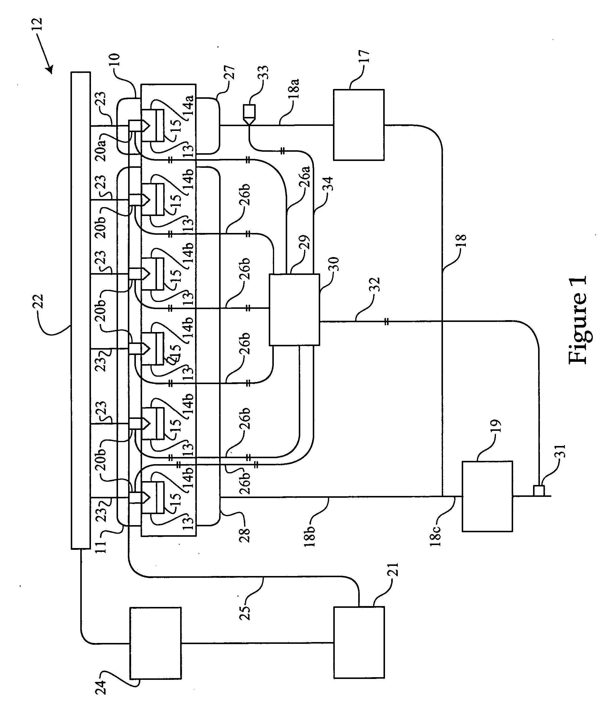
[0015] Referring to FIG. 1, there is shown a schematic representation of an exhaust after-treatment system 12, according to the present disclosure. The exhaust after-treatment system 12 includes at least one combustion chamber 14 defined by an engine cylinder 13. Although the present disclosure contemplates only one combustion chamber 14, the exhaust after-treatment system 12 preferably includes a plurality of combustion chambers 14 divided into a first portion of combustion chambers 14a and a second portion of combustion chambers 14b. In the illustrated embodiment, the engine 10 includes six cylinders 13 defining the six combustion chambers 14 with one combustion chamber within the first portion 14a and five combustion chambers within the second portion 14b. For purposes of this discussion, the combustion chamber within the first portion 14a will be referred to as the first combustion chamber 14a. Those skilled in the art will appreciate that the number of combustion chambers 14 in...


PUM


Abstract

Often NOx selective catalysts that use ammonia to reduce NOx within exhaust to a harmless gas require on-board storage of ammonia which can be hazardous and inconvenient. In order to generate ammonia in exhaust, the present disclosure increases a NOx concentration in exhaust from at least one combustion chamber, at least in part, by injecting fuel in a predetermined increased NOx generation sequence that includes a first injection during non-auto ignition conditions and a second injection during auto ignition conditions. At least a portion of the NOx is converted to ammonia by passing at least a portion of the exhaust with the increased NOx concentration over an ammonia-producing catalyst.

Description

U.S. GOVERNMENT RIGHTS [0001] This disclosure was made with government support under the terms of Contract No. DE-FC05-97OR22605 awarded by the Department of Energy. The government may have certain rights in this invention.TECHNICAL FIELD [0002] The present disclosure relates generally to exhaust after-treatment systems with on-board ammonia generation, and more specifically to increasing NOx concentrations via combustion for generating ammonia used with an exhaust after-treatment systems. BACKGROUND [0003] In order to meet increasingly stringent federal regulations of NOx and other undesirable emissions, engineers are constantly seeking new strategies of reducing the production of undesirable emissions. One method of reducing NOx emissions is NOx selective catalytic reduction (SCR) systems. These systems use ammonia (NH3) to reduce NOx to nitrogen (N2) and water. Although these systems can reduce NOx emissions, NOx selective catalytic reduction systems often require an ammonia stor...

Claims


Application Information

Patent Timeline
IPC IPC(8): C01C1/00
CPCB01D53/90B01D53/9409B01D53/9495C01C1/04F01N3/2073F01N13/107F01N2240/25F01N2610/03F02D41/0235F02D41/402F02D2250/36F02M45/086F02M61/182F02M63/0064F02M2200/46F01N13/009F01N13/011F02M47/027
Inventor DRISCOLL, JOSHROBEL, WADE J.BROWN, CORY A.URVEN, ROGER L. JR.
Owner CATERPILLAR INC
Why Eureka
Try Eureka