Link plate for a plate-link chain
a technology of plate-link chain and link plate, which is applied in the direction of driving chains, belts/chains/gearrings, chain elements, etc., can solve the problems of more severe loading and damage to the link plate, and achieve the effect of increasing the anti-turning protection of the rocker members in the openings of the link plate, increasing fatigue strength, and increasing tractive for
- Summary
- Abstract
- Description
- Claims
- Application Information
AI Technical Summary
Benefits of technology
Problems solved by technology
Method used
Image
Examples
first embodiment
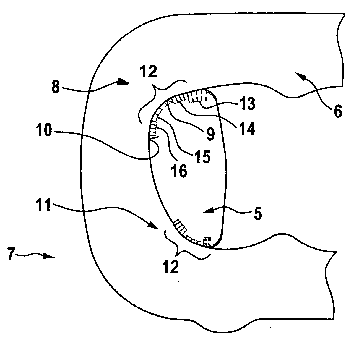
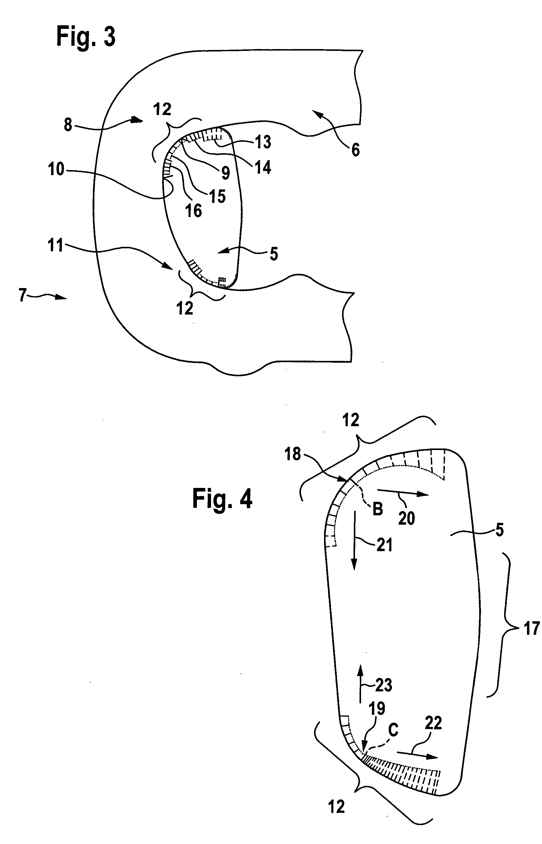
[0043]FIG. 3 of the drawings shows an enlarged representation of a rocker member 5 and a link plate 6 of a plate-link chain 7 according to the present invention.
[0044] As can be seen in FIG. 3, there are two contact surface regions 8 and 11 between rocker member 5 and link plate 6, contact surface region 8 being formed by a contact surface 9 on rocker member 5 and a contact surface 10 on the link plate 6. In a similar manner, contact surface region 11 is composed of a contact surface on rocker member 5 and a complimentarily-formed contact surface on link plate 6.
[0045] Rocker member 5 and link plate 6 are in contact with each other at contact surface 9 and contact surface 10 to transmit force. Since link plate 6 has a certain thickness in the direction transverse to the drawing plane of FIG. 3, and a plurality of those link plates lying side by side are in contact with the same rocker member 5, the tractive force transmitted by plate-link chain 7 is distributed over the individual ...
second embodiment
[0048]FIG. 4 of the drawings shows a rocker member 5 of a plate-link chain according to the present invention, wherein that rocker member is a rocker member of a plate-link chain for a belt-driven conical-pulley transmission.
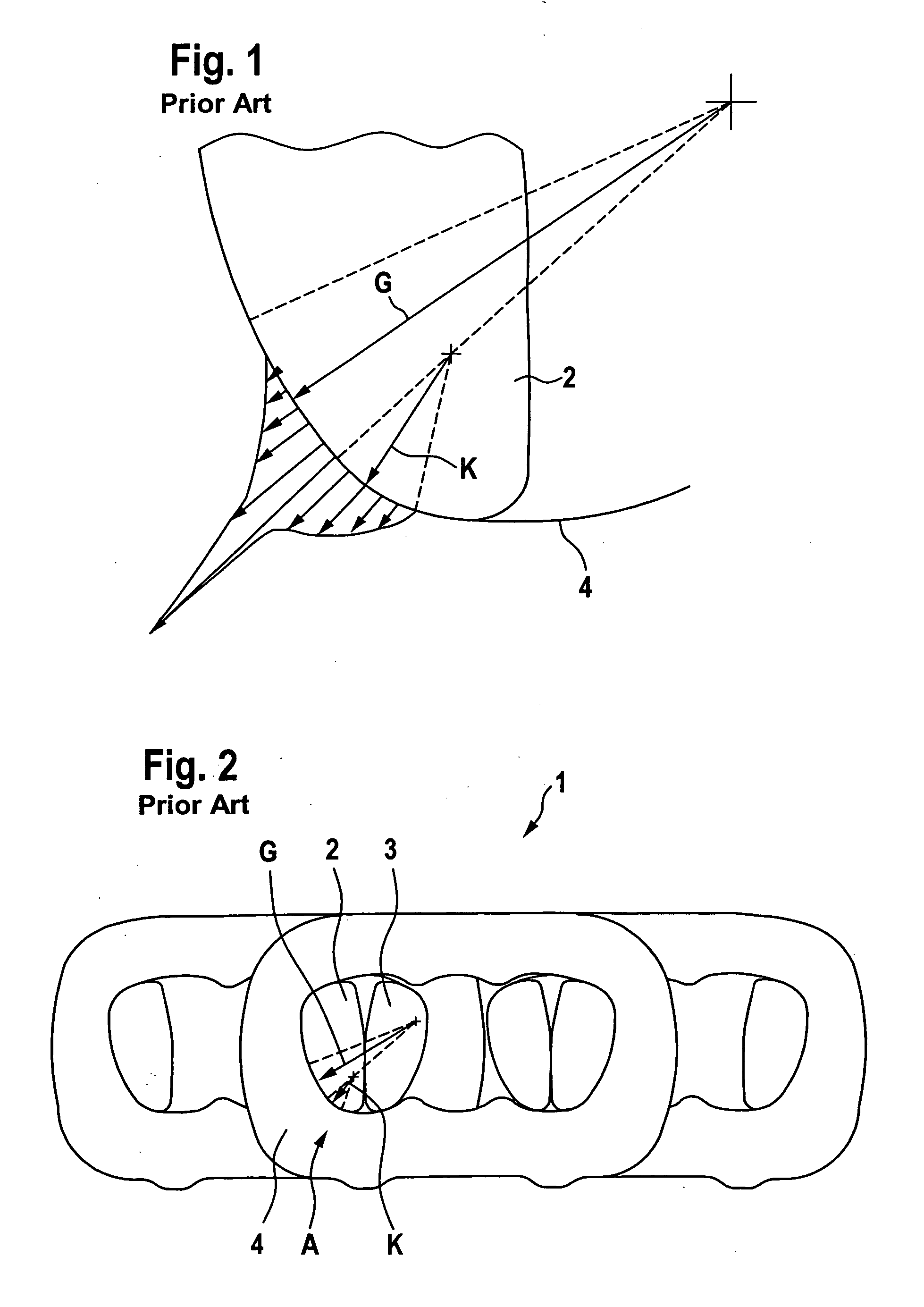
[0049] On rocker member 5, reference numeral 17 designates the roller surface with which rocker member 5 rolls against the opposing rocker member (again, a pair of rocker members is involved), the basic configuration being visible on the basis of FIG. 2 of the drawing. Rocker member 5, in turn, has two contact surfaces 18, 19, which are positioned against complimentarily-formed contact surfaces of a link plate (not shown). The upper contact surface 18 has a point designated as B at which the maximum curvature is located, i.e., where the radius of curvature, which is again shown perpendicular to contact surface 18 by way of explanation, is at its minimum. Starting from point B the radius of curvature increases in both directions, so that the curvature becomes con...
PUM
 Abstract
Description
Claims
Application Information
 - R&D
- Intellectual Property
- Life Sciences
- Materials
- Tech Scout
- Unparalleled Data Quality
- Higher Quality Content
- 60% Fewer Hallucinations
Browse by: Latest US Patents, China's latest patents, Technical Efficacy Thesaurus, Application Domain, Technology Topic, Popular Technical Reports.
© 2025 PatSnap. All rights reserved.Legal|Privacy policy|Modern Slavery Act Transparency Statement|Sitemap|About US| Contact US: help@patsnap.com


