Cryogenic air separation process with excess turbine refrigeration

a technology of cryogenic air separation and turbine refrigeration, which is applied in the direction of refrigeration and liquid storage, lighting and heating equipment, solidification, etc., can solve the problem that the booster air compressor consumes a large amount of energy

Inactive Publication Date: 2007-05-03
PRAXAIR TECH INC
View PDF19 Cites 19 Cited by
  • Summary
  • Abstract
  • Description
  • Claims
  • Application Information

AI Technical Summary

Benefits of technology

[0008] As used herein, the term “column” means a distillation or fractionation column or zone, i.e. a contacting column or zone, wherein liquid and vapor phases are countercurrently contacted to effect separation of a fluid mixture, as for example, by contacting of the vapor and liquid phases on a series of vertically spaced trays or plates mounted within the column and/or on packing elements such as

Problems solved by technology

As such, when higher pressure oxygen is required as a product,

Method used


Image

  • Cryogenic air separation process with excess turbine refrigeration
  • Cryogenic air separation process with excess turbine refrigeration
  • Cryogenic air separation process with excess turbine refrigeration

Examples


Embodiment Construction

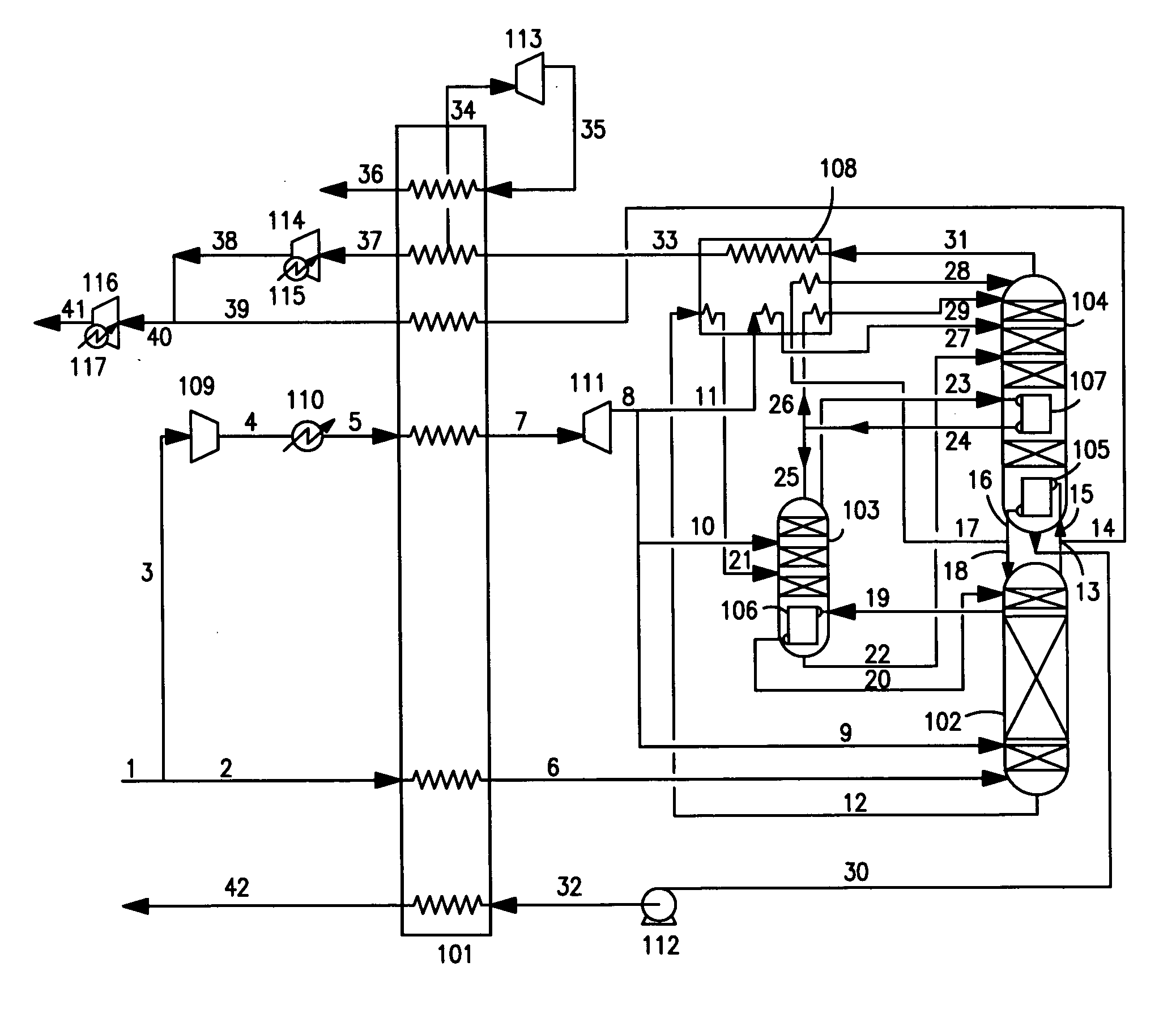
[0019] In general the liquid oxygen pumped cryogenic air separation method of this invention is characterized by an aggregate warm end temperature difference (WEDT) that is at least 2K more than the primary heat exchanger's minimum internal temperature difference (PHX pinch DT). More preferably, the difference between the WEDT and the PHX pinch DT will be greater than 3K, and most preferably it is greater than 4K. The extra refrigeration required for this invention is generated by the expansion of a process gas across a turbine. In many cases the savings that will be realized by reducing the compression energy of the condensing air stream will more than offset the penalties associated with extra refrigeration production. This is particularly the case at higher oxygen boiling pressures.

[0020] The invention will be described in greater detail with reference to the Drawings. Referring now to FIG. 1, compressed, chilled, pre-purified feed air 1, which has been compressed in a main air ...


PUM


Abstract

A process for carrying out cryogenic air separation wherein liquid oxygen is pressurized and vaporized against condensing feed air to produce oxygen gas product wherein excess plant refrigeration is generated such that the aggregate warm end temperature difference of the process exceeds the minimum internal temperature difference of the primary heat exchanger by at least 2K.

Description

TECHNICAL FIELD [0001] This invention relates generally to cryogenic air separation and, more particularly, to cryogenic air separation to produce oxygen product. BACKGROUND ART [0002] The separation of air into its constituent components by distillation occurs at cryogenic temperatures, and requires some amount of refrigeration. This refrigeration is typically generated by the expansion of a process gas across a turbine. When designing air separation processes, the amount of refrigeration generated by expansion is typically kept at a minimum, as all forms of refrigeration generation are penal to the process, either by degrading the efficiency of the separation or by requiring more compression energy than is minimally required by the needs of the plant's distillation columns. The efficiency of refrigeration usage for a plant is reflected by the temperature difference between the streams entering and leaving the plant. This temperature difference is referred to as the aggregate warm ...

Claims


Application Information

Patent Timeline
IPC IPC(8): F25J3/00
CPCF25J3/0409F25J3/04187F25J3/04315F25J3/04387F25J3/04448F25J2200/20F25J2200/50F25J2200/54F25J2240/10F25J2290/12
Inventor RANKIN, PETER JAMESPROSSER, NEIL MARK
Owner PRAXAIR TECH INC
Why Eureka
Try Eureka