
Noise eliminating apparatus, weight measurement apparatus, method of eliminating noise, and method of designing digital filter

a noise elimination and noise technology, applied in the field of filtering technique, can solve the problems of increasing the circuit scale of the digital filter, the frequency change of the natural frequency noise caused by the change in the weight of the article is too significant to neglect, and the noise is easily and appropriately eliminated, so as to achieve the effect of increasing the circuit scale necessary and increasing the nois

Inactive Publication Date: 2007-05-03
ISHIDA CO LTD
View PDF6 Cites 13 Cited by
  • Summary
  • Abstract
  • Description
  • Claims
  • Application Information

AI Technical Summary

Benefits of technology

[0014] It is an object of the present invention to provide a filtering technique which makes it possible to easily and appropriately eliminate a noise without increasing a scale of a circuit necessary for a filtering process even if a noise frequency is liable to be changed.
[0016] The present invention is also intended for a method of eliminating a noise.
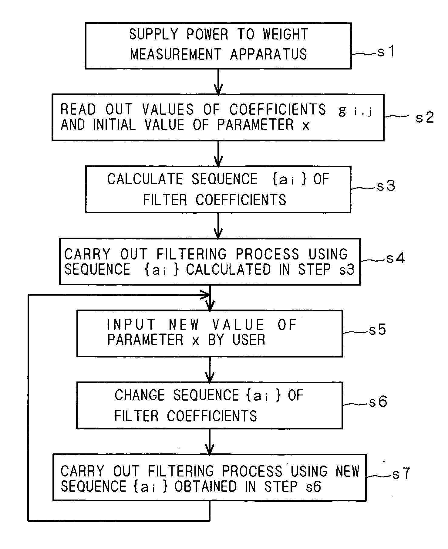
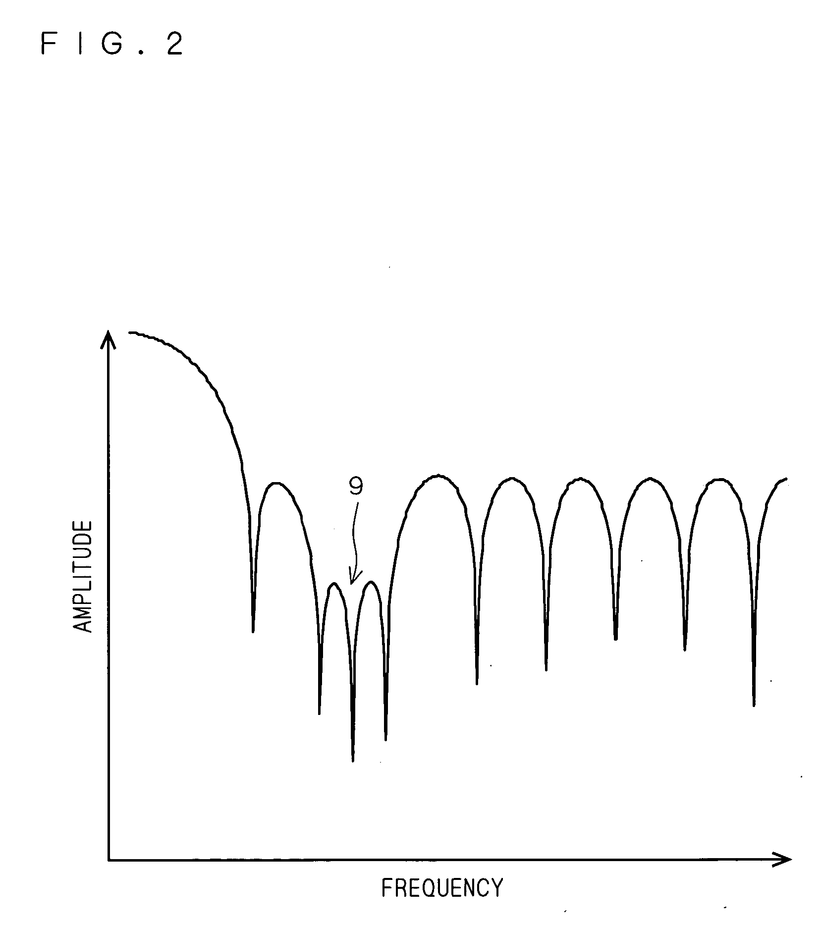
[0017] The filter coefficients can be changed by using the parameter specifying the band position of the attenuation band which is physical and thus easy to grasp. As such, even when a frequency which must be attenuated is changed, it is possible to easily move the attenuation band by referring to information about a new frequency which must be attenuated. Accordingly, a frequency of a noise, which is liable to be changed, can be filtered out easily and appropriately. Further, since the filter coefficients are obtained by the arithmetic expression, there is no need of preparing multistage filters or previously storing filter coefficients representing different characteristics. This makes it possible to reduce a scale of a circuit necessary for the filtering process and to thus provide a low cost noise eliminating apparatus to users. Moreover, since a plurality of attenuation bands can be specified, a plurality of causes causing a big noise and varying can be dealt with appropriately.
[0021] The filter coefficients can be changed by using the parameter specifying the band position of the attenuation band which is physical and thus easy to grasp. As such, even when a frequency which must be attenuated is changed, it is possible to easily move the attenuation band by referring to information about a new frequency which must be attenuated. Accordingly, a frequency of a noise, which is liable to be changed, can be filtered out easily and appropriately. Further, since the filter coefficients are obtained by the arithmetic expression, there is no need of preparing multistage filters. This makes it possible to reduce a scale of a circuit of the digital filter. Moreover, since a plurality of attenuation bands can be specified, a plurality of causes causing a big noise and varying can be dealt with appropriately.

Problems solved by technology

Also, in measuring a load of a transfer system, a noise caused due to vibration of a rotation system such as a motor for driving a conveyor belt or a transfer roller, or an electrical noise associated with a commercial power supply, works as a vibration noise which is superimposed on a weighing signal.
Thus, if an article weight or a tare is changed, it results in change in a frequency of a natural frequency noise associated with the weight sensor.
For this reason, such change in frequency of a natural frequency noise caused due to change in article weight has become too significant to neglect.
In this regard, to initially design a digital filter which allows for addition of a specification in a weight measurement apparatus requires preparing numerous multistage moving average filters, which results in increase of a circuit scale of the digital filter.
However, this alternative requires previously storing numerous filter coefficients in order to surely eliminate a vibration noise at a wide range of frequencies, which results in increase of a circuit scale of a memory for storing the filter coefficients.

Method used


Image

  • Noise eliminating apparatus, weight measurement apparatus, method of eliminating noise, and method of designing digital filter
  • Noise eliminating apparatus, weight measurement apparatus, method of eliminating noise, and method of designing digital filter
  • Noise eliminating apparatus, weight measurement apparatus, method of eliminating noise, and method of designing digital filter

Examples


Embodiment Construction

Description of Conventional Art of the Present Invention

[0035] Before describing a preferred embodiment according to the present invention, a weight measurement apparatus serving as conventional art of the present invention will be described. The conventional art is disclosed in Japanese Patent Application Laid-Open No. 2004-150883 filed by the applicant of the present invention.

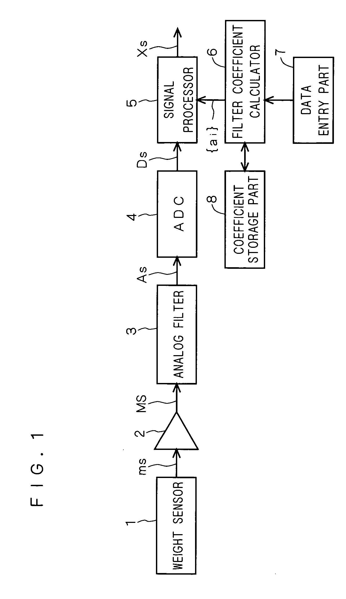
[0036]FIG. 1 is a block diagram illustrating the structure of the weight measurement apparatus according to the conventional art. As illustrated in FIG. 1, the weight measurement apparatus according to the conventional art includes a weight sensor 1 such as a strain gauge load cell or a force balance, an amplifier 2, an analog filter 3, an A / D converter (which will be hereinafter referred to as an “ADC”) 4, a signal processor 5, a filter coefficient calculator 6, a data entry part 7 and a coefficient storage part 8.

[0037] The weight sensor 1 detects a weight of an object under measurement, which is notifi...


PUM


Abstract

A filter coefficient calculator of a weight measurement apparatus calculates filter coefficients using a predetermined arithmetic expression and outputs them to a signal processor. The signal processor carries out a filtering process on a weighing signal using the filter coefficients. The arithmetic expression includes a spectrum parameter specifying a band position of an attenuation band where attenuation must be locally enhanced. A user can input a value of the parameter via a data entry part. Each band is specified by the spectrum parameter not as the lowest limit value of a normalized angular frequency, but as the amount of deviation (the amount of displacement) from its center frequency.

Description

BACKGROUND OF THE INVENTION [0001] 1. Field of the Invention [0002] The present invention relates to a filtering technique carried out by using a digital filter. [0003] 2. Description of the Background Art [0004] A weight measurement apparatus for measuring a weight of an article typically employs a weight sensor such as a strain gauge load cell or a force balance. The weight sensor has a natural frequency which is subject to a total weight of a weight of an article and a tare thereof. When external vibration at frequencies in a band including the natural frequency acts upon a weight measurement system, external vibration at a frequency close to the natural frequency is amplified, to work as a vibration noise, which then emerges in a weighing signal output from the weight sensor. It is noted that such a vibration noise will be hereinafter referred to as a “natural frequency noise” throughout the present specification. [0005] Also, in measuring a load of a transfer system, a noise ca...

Claims


Application Information

Patent Timeline
IPC IPC(8): G01F25/00
CPCG01G23/10H03H17/0294H03H2017/0297
Inventor AIKAWA, NAOYUKIWAKASA, YUKIONAKATANI, MAKOTO
Owner ISHIDA CO LTD
Learn More