
Control apparatus and control method for internal combustion engine

a control apparatus and internal combustion engine technology, applied in combustion engines, machines/engines, valve arrangements, etc., can solve the problems of increasing differences in air quantity and internal egr for example between cylinders, easy or difficult changes of valve phase, etc., and achieving the effect of restricting the occurrence of non-uniformity of cylinders

Inactive Publication Date: 2007-05-03
TOYOTA JIDOSHA KK
View PDF3 Cites 0 Cited by
  • Summary
  • Abstract
  • Description
  • Claims
  • Application Information

AI Technical Summary

Benefits of technology

[0009] An object of the present invention is to provide a control apparatus or the like for an internal combustion engine that can restrain occurrence of nonuniformity of cylinders with respect to each other in terms of intake air quantity and internal EGR quantity.
[0011] In accordance with the present invention, in the case where the torque acts in the opposite direction to the camshaft rotational direction, the phase in which the valve is closed is advanced and, in the case where the torque acts in the camshaft rotational direction, the phase is retarded. Thus, for a cylinder, in the case where the torque acting in the opposite direction to the camshaft rotational direction could cause delay of the phase (timing) in (at) which the intake valve or exhaust valve is closed, the phase in which the intake valve or exhaust valve is closed can be advanced. Accordingly, occurrence of delay of the phase in which the intake valve or exhaust valve is closed can be restrained. Further, for a cylinder, in the case where the torque acting in the camshaft rotational direction could cause advance of the phase in which the intake valve or exhaust valve is closed, the phase in which the intake or exhaust valve is closed can be retarded. Accordingly, occurrence of advance of the phase in which the intake valve or exhaust valve is closed can be restrained. Thus, the control apparatus for the internal combustion engine can be provided that can restrain occurrence of displacement of the phase in which the intake valve or exhaust valve of each cylinder is actually closed with respect to a phase determined under control, and can restrain occurrence of nonuniformity of cylinders with respect to each other in terms of quantity of air taken into the cylinder and internal EGR quantity.
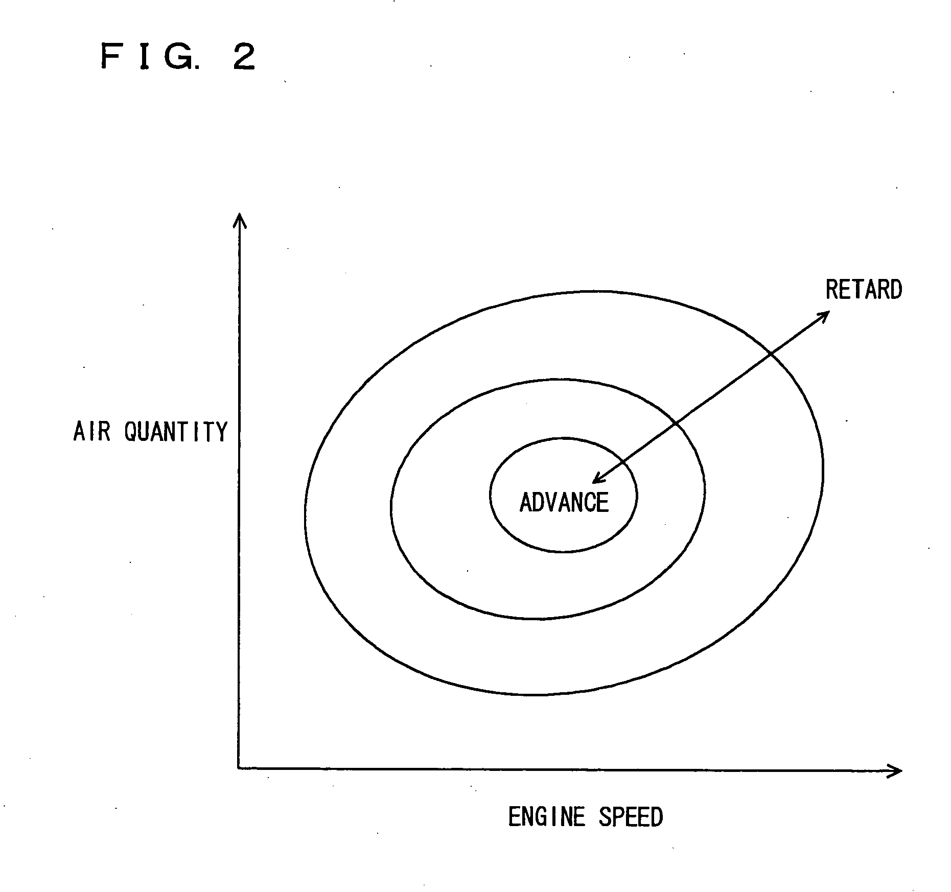
[0013] In accordance with the present invention, as the torque acting in the opposite direction to the camshaft rotational direction is larger, the phase of the intake valve or exhaust valve is advanced to a greater extent. Further, as the torque acting in the camshaft rotational direction is larger, the phase of the intake valve or the exhaust valve is retarded to a grater extent. Accordingly, as delay in phase in which the intake valve or exhaust valve is closed is larger, the phase in which the intake valve or exhaust valve is closed can be advanced to a greater extent. Further, as advance in phase in which the intake valve or exhaust valve is closed is larger, the phase in which the intake valve or exhaust valve is closed can be retarded to a greater extent. Thus, for each cylinder, occurrence of displacement of the phase in which the intake valve or exhaust valve is actually closed with respect to a phase determined under control can be restrained, and occurrence of nonuniformity of cylinders with respect to each other in terms of intake air quantity and internal EGR quantity can be restrained.
[0015] In accordance with the present invention, as a higher camshaft rotational speed causes a larger torque acting in the opposite direction to the camshaft rotational direction, the phase of the intake valve or exhaust valve is advanced to a greater extent. Further, as a higher camshaft rotational speed causes a larger torque acting in the camshaft rotational direction, the phase of the intake valve or exhaust valve is retarded to a greater extent. Accordingly, as delay in phase in which the intake valve or exhaust valve is closed is larger, the phase in which the intake valve or exhaust valve is closed can be advanced to a greater extent. Further, as advance in phase in which the intake valve or exhaust valve is closed is larger, the phase in which the intake valve or exhaust valve is closed can be retarded to a greater extent. Thus, for each cylinder, occurrence of displacement of the phase in which the intake valve or exhaust valve is actually closed with respect to a phase determined under control can be restrained, and occurrence of nonuniformity of cylinders with respect to each other in terms of intake air quantity and internal EGR quantity can be restrained.
[0017] In accordance with the present invention, as a higher load of the internal combustion engine causes a larger torque acting in the opposite direction to the camshaft rotational direction, the phase of the intake valve or exhaust valve is advanced to a greater extent. Further, as a higher load of the internal combustion engine causes a larger torque acting in the camshaft rotational direction, the phase in which the intake valve or exhaust valve is closed can be retarded to a greater extent. Accordingly, as delay in phase in which the intake valve or exhaust valve is closed is larger, the phase in which the intake valve or exhaust valve is closed can be advanced to a greater extent. Further, as advance in phase in which the intake valve or exhaust valve is closed is larger, the phase in which the intake valve or exhaust valve is closed can be retarded to a greater extent. Thus, for each cylinder, occurrence of displacement of the phase in which the intake valve or exhaust valve is actually closed with respect to a phase determined under control can be restrained, and nonuniformity of cylinders with respect to each other in terms of intake air quantity and internal EGR quantity can be restrained.

Problems solved by technology

In other words, depending on the direction in which the cam torque is exerted, the phase of the valve may be easy to change or difficult to change by rotation of the camshaft.
In the cylinder having its intake valve closed in the delayed phase, the quantity of air pushed back from the cylinder into the intake manifold as the piston is lifted increases, resulting in a decrease in final quantity of air sucked into the cylinders.
Consequently, the phase in which the intake valve or exhaust valve is actually closed is further displaced from a phase determined under control, which could increase differences in air quantity and internal EGR for example between cylinders.

Method used


Image

  • Control apparatus and control method for internal combustion engine
  • Control apparatus and control method for internal combustion engine
  • Control apparatus and control method for internal combustion engine

Examples


Embodiment Construction

[0026] With reference to the drawings, embodiments of the present invention are hereinafter described. In the following description, like components are denoted by like reference characters. They are also named identically and function identically. Therefore, a detailed description thereof is not repeated.

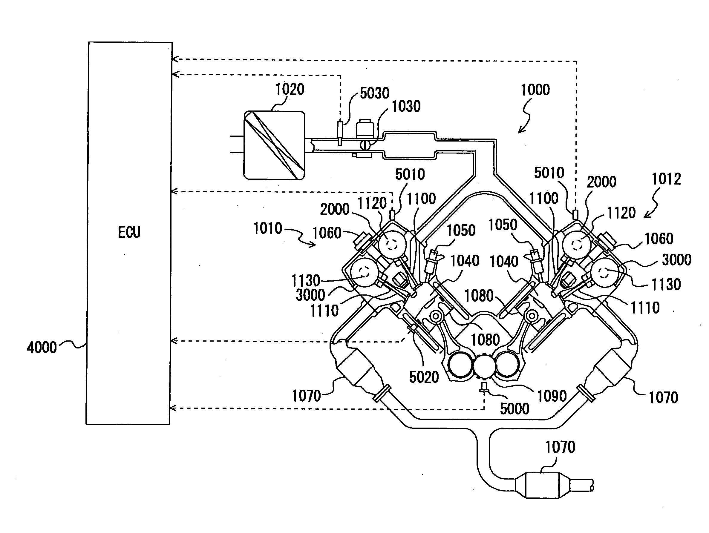
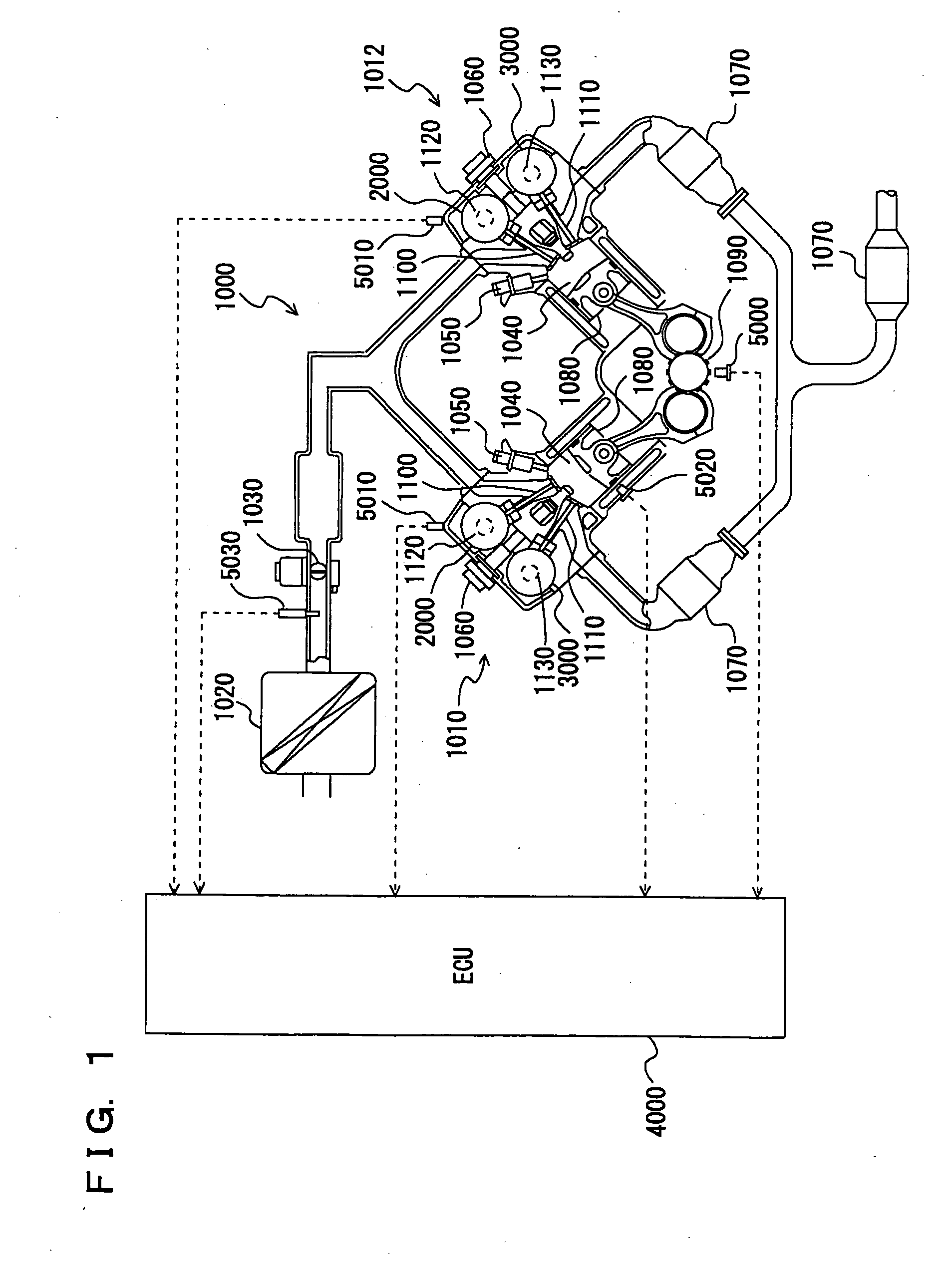
[0027] Referring to FIG. 1, a description is given of an engine of a vehicle on which a control apparatus is mounted, according to an embodiment of the present invention. The control apparatus in the present embodiment is implemented for example by means of a program executed by an ECU (Electronic Control Unit) 4000 shown in FIG. 1.

[0028] Engine 1000 is a V-type 8-cylinder engine having an “A” bank 1010 and a “B” bank 1012 each including a group of four cylinders. Here, any engine other than the V8 engine may be used.

[0029] Into engine 1000, air is sucked from an air cleaner 1020. The quantity of sucked air is adjusted by a throttle valve 1030. Throttle valve 1030 is an electron...


PUM


Abstract

An ECU executes a program including the steps of detecting the crank angle, advancing, at a crank angle at which the cam torque is exerted in the direction opposite to the rotational direction of an intake camshaft, the phase in which the intake valve is closed and retarding, at a crank angle at which the cam torque is exerted in the rotational direction of the intake camshaft, the phase in which the intake valve is closed.

Description

[0001] This nonprovisional application is based on Japanese Patent Application No. 2005-318509 filed with the Japan Patent Office on Nov. 1, 2005, the entire contents of which are hereby incorporated by reference. BACKGROUND OF THE INVENTION [0002] 1. Field of the Invention [0003] The present invention relates to control of an internal combustion engine. In particular, the invention relates to the technique of advancing or retarding a phase in which a valve is closed, according to a torque exerted on a camshaft that drives the valve. [0004] 2. Description of the Background Art [0005] An internal combustion engine has been known that has such valves as intake valves and exhaust valves opened and closed by rotation of camshafts. In such an internal combustion engine, as the camshaft rotates, a reaction force from the valve causes a torque acting on the camshaft (the torque is also referred to as cam torque hereinafter). As the valve is opened, the cam torque is exerted in the directio...

Claims


Application Information

Patent Timeline
IPC IPC(8): F01L1/34
CPCF01L1/34F01L2800/00F01L2810/03F02D13/0207Y02T10/18Y02T10/12
Inventor YOKOYAMA, YUUMORIYA, YOSHIHITOITOH, YUJIHASEGAWA, TADAOHATTORI, MASAYOSHI
Owner TOYOTA JIDOSHA KK
Learn More