Reconfigurable heel elevator

a technology of elevators and heel, applied in the field of reconfigurable elevators, can solve the problems of ulcers, prone to ulcers, osteomyelitis and even limb amputation, etc., and achieve the effect of reducing or mitigating the pressure on the individual's heel

Active Publication Date: 2007-05-03
SUN SCI
View PDF41 Cites 19 Cited by
  • Summary
  • Abstract
  • Description
  • Claims
  • Application Information

AI Technical Summary

Benefits of technology

[0011] Various embodiments of the present invention provide such advancements and overcome the above mentioned and other problems and limitations of the background art, by providing a method and appar

Problems solved by technology

Heel ulcers are costly and, if not treated promptly and properly, may lead to osteomyelitis and even limb amputation.
Pressure ulcers of the heel may occur in individuals who for any reason spend extended periods of time in bed, and/or who may suffer from certain diseases or ailments making them prone to ulcers even without extended bedrest.
For instance, heel ulcers often occur in patients with immobile legs due to health care problems such as fractured hips, joint replacement surgery, spinal cord injury, Guillain-Barré syndrome, or stroke, who do not move their legs because of paralysis, weakness, or pain.
Diabetic patients are also susceptible to heel ulcers, as these patients may not feel foot pressure or injuries because of peripheral neuropathy, increasing the likelihood for heel ulcers even without extended bedrest or leg elevation.
Further, immobile diabetic patients may have trouble moving their legs, thus exascerbating the decubitus conditions that cause heel ulcers.
Patients who have leg spasms, or who are otherwise confused, may rub their heels on the bed and abrade the heel.
Patients may also dig their heels

Method used


Image

  • Reconfigurable heel elevator
  • Reconfigurable heel elevator
  • Reconfigurable heel elevator

Examples


Embodiment Construction

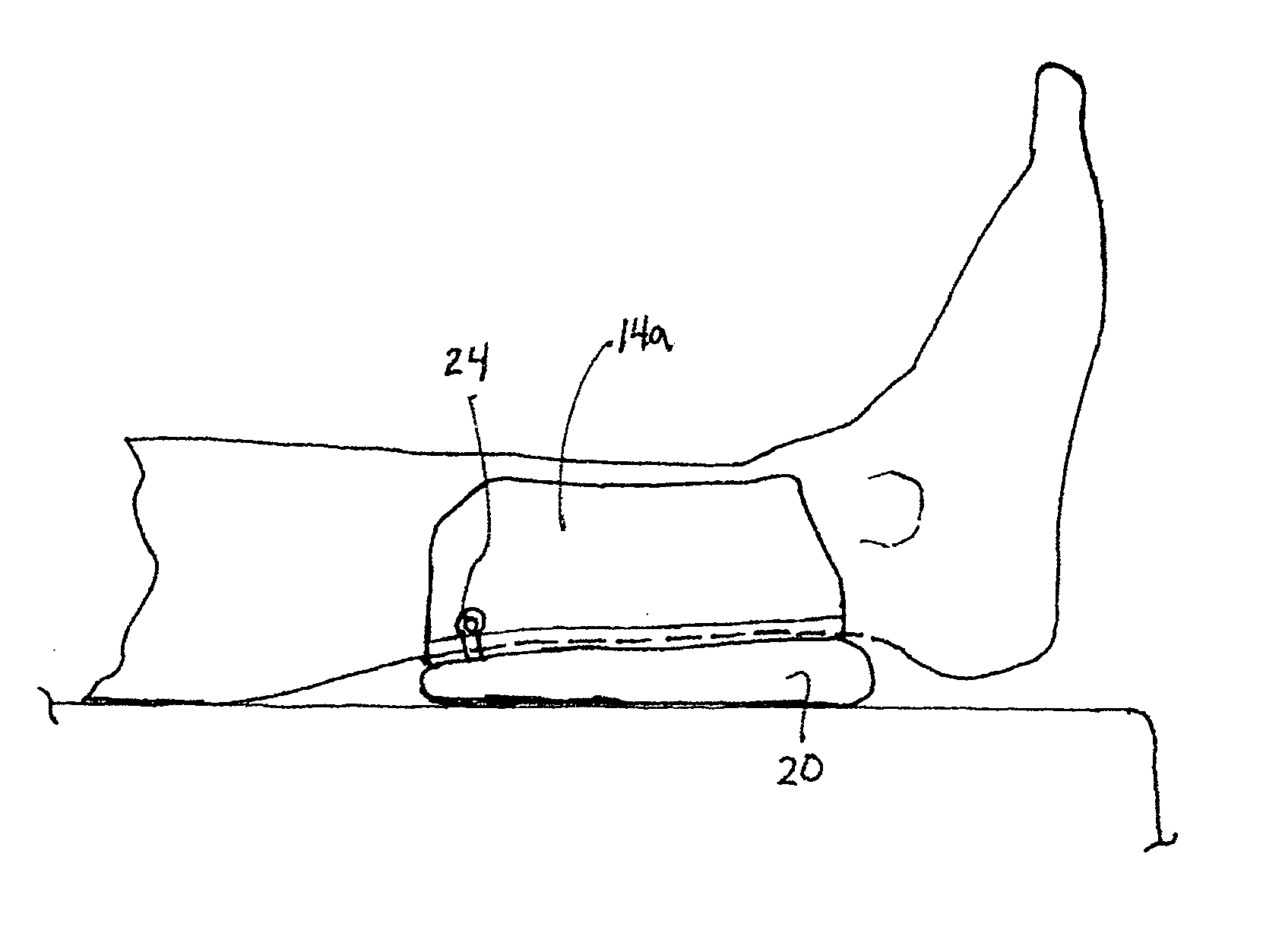
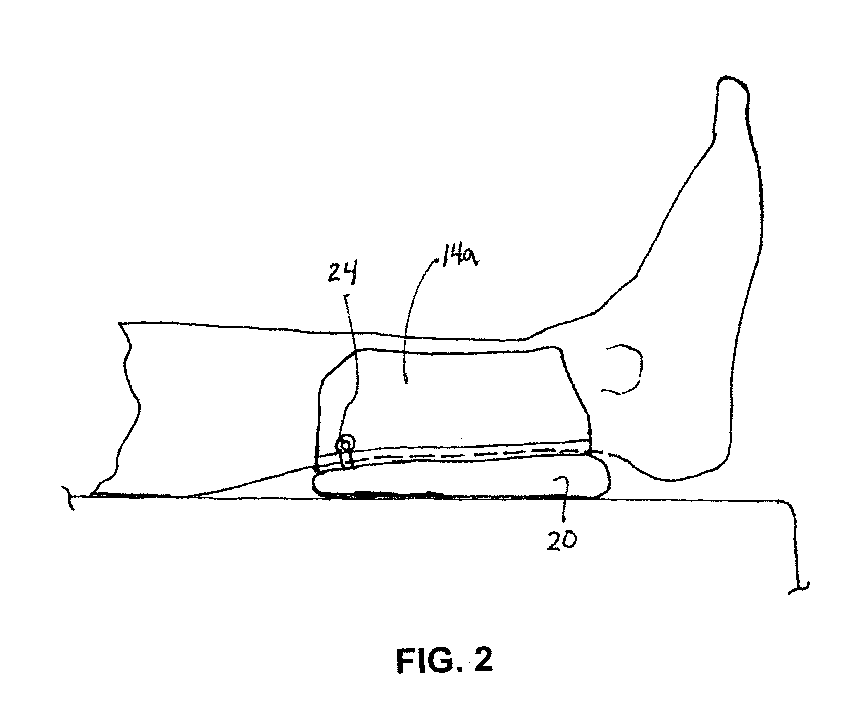
[0030] As will be understood and more fully appreciated from the ensuing description, embodiments of the present invention are configured for attachment to the lower leg to provide for reducing or eliminating pressure on the heel region of the foot when the leg or foot is positioned such that the heel is in contact with an underlying surface (e.g., a bed) or would be in contact with an underlying surface but for the presence of the device. That is, as will be further understood below, while embodiments of the present invention may be implemented to sufficiently elevate the foot to provide for spatial separation of the heel from an underlying surface that the heel would otherwise rest upon, such and other embodiments of the present invention need not be used to provide such spatial separation of the heel, but rather may be advantageously used to reduce pressure on the heel even if the heel is in contact with an underlying surface. Additionally, even when the foot may be cantilevered ...


PUM


Abstract

A method and apparatus for eliminating or otherwise reducing or mitigating pressure on an individual's heel while the leg is in an extended position, while allowing for ambulation without completely removing the device. An apparatus comprises a support member configured to be attached to a lower leg portion of an individual between the calf and heel region, the support member having an inner surface portion to be disposed facing the leg when attached thereto, and having an opposite outer surface; and a reconfigurable elevation member configured (i) to be disposed at the outer surface of the support member such that when the support member is attached to the lower leg portion of the individual the elevation member is selectively capable of providing elevation of the heel from an underlying surface in the event that the lower leg portion is extended above the underlying surface, and (ii) to be reconfigured for ambulation without removing said support member from the lower leg. In some implementations, the reconfigurable elevation member is integral with the support member and is inflatable and deflatable. In other implementations, the reconfigurable elevation member is removably attachable to the support member, and may be removed for ambulation while the support member remains securely in place such that the elevation member may be reattached thereto.

Description

[0001] This application claims the benefit of US Provisional Application No. 60 / 730,766, filed Oct. 27, 2005, which is incorporated herein by reference in its entirety.BACKGROUND OF THE INVENTION [0002] 1. Field of the Invention [0003] The present invention relates generally to preventing, treating, and / or relieving decubitus ulcers and, more particularly, to a device that reduces or eliminates heel pressure while the leg is extended, and that allows for and does not impede ambulation while the device is in place. [0004] 2. Background Information [0005] Because of its thin layer of subcutaneous tissue between the skin and bone, the heel is the second most common site for pressure ulcer development (after the sacrum). Heel ulcers are costly and, if not treated promptly and properly, may lead to osteomyelitis and even limb amputation. Pressure ulcers of the heel may occur in individuals who for any reason spend extended periods of time in bed, and / or who may suffer from certain diseas...

Claims


Application Information

Patent Timeline
IPC IPC(8): A61G15/00
CPCA61G7/0755A61G13/12A61G13/1245A61G13/125A61G13/1265A61G15/12
Inventor RAVIKUMAR, SUNDARAM
Owner SUN SCI
Why Eureka
Try Eureka