Photocathode
a photocathode and cathode technology, applied in the field of photocathodes, can solve the problems of not having sensitivity to visible laser light wavelengths as well as wavelengths of ultraviolet band
- Summary
- Abstract
- Description
- Claims
- Application Information
AI Technical Summary
Benefits of technology
Problems solved by technology
Method used
Image
Examples
first embodiment
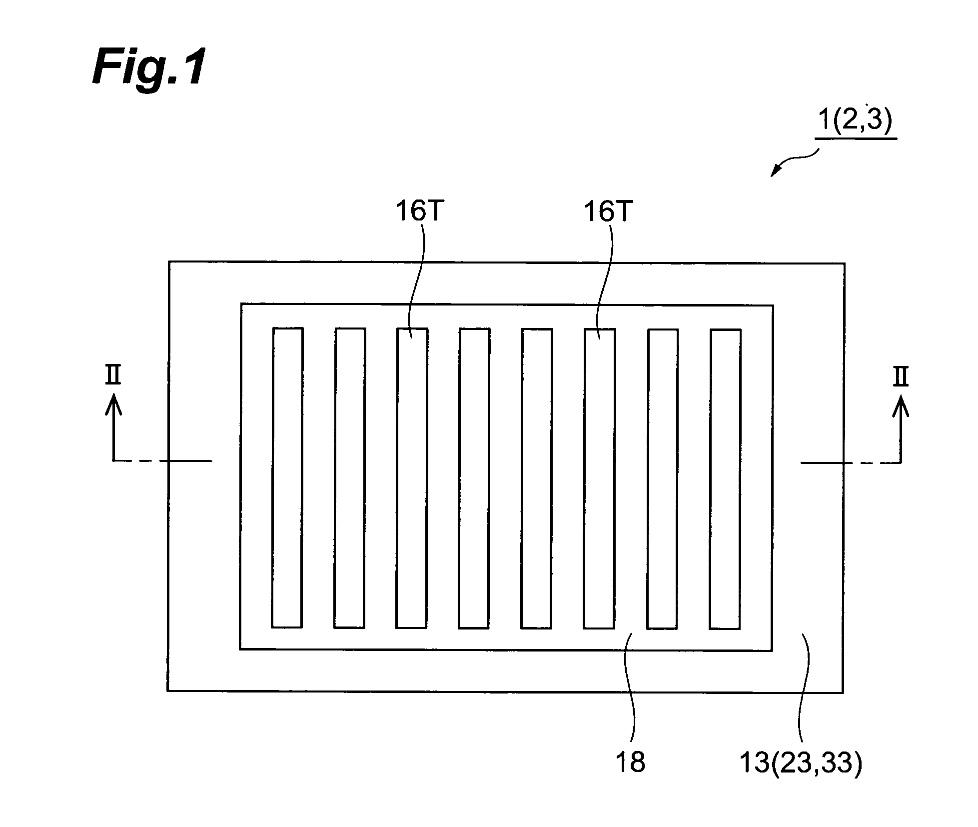
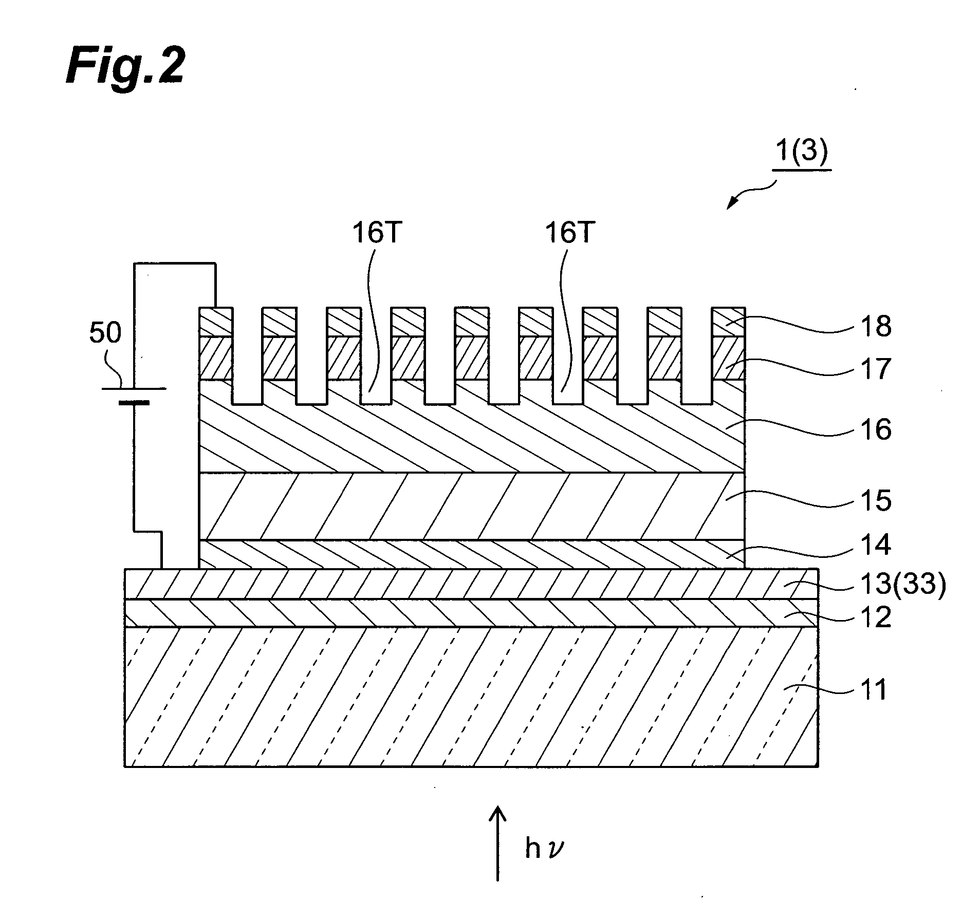
[0029]FIG. 1 is a plan view of a transmission-type semiconductor photocathode 1 according to a first embodiment, and FIG. 2 is a sectional view taken on line II-II of FIG. 1.
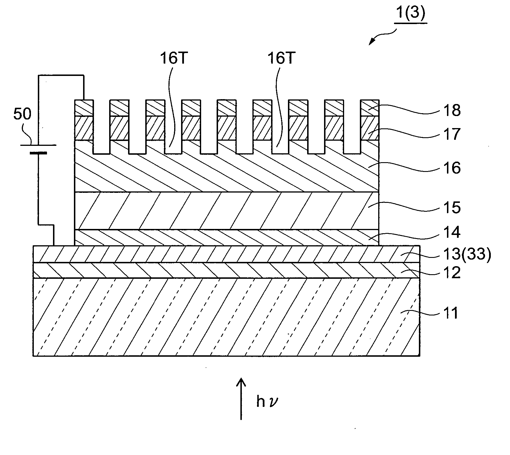
[0030] The semiconductor photocathode 1 includes a transparent substrate 11, an intermediate film (insulating film or antireflection film) 12, a first electrode 13, a window layer 14, a light absorbing layer 15, an electron emission layer 16, a contact layer 17, and a second electrode 18. The window layer 14, the light absorbing layer 15, the electron emission layer 16, and the contact layer 17 are arranged as a semiconductor multilayer film that serves the role of photoelectric conversion.
[0031] The transparent substrate 11 is formed of a material that is not restricted in the short wavelength sensitivity end and transmits an incident light hv of a wide wavelength band spanning from an ultraviolet band to a near infrared band. As the material of the transparent substrate 11, for example, glass or quartz is us...
second embodiment
[0059] A transmission-type semiconductor photocathode according to a second embodiment of the present invention shall now be described.
[0060]FIG. 6 is a sectional view of the transmission-type semiconductor photocathode 2 according to the second embodiment. Because the plan view of the semiconductor photocathode 2 is the same as FIG. 1, description shall be omitted by providing elements corresponding to those of FIG. 1 with the same symbols.
[0061] A difference of the present embodiment with respect to the first embodiment is a first electrode 23 that is disposed at the light incidence side, and other elements are the same as those of the first embodiment. With the present embodiment, the first electrode 23 differs from that of the first embodiment in being arranged as a metal material layer having openings 23B. Specifically, as shown in the plan view of FIG. 7, by providing the plurality of openings 23B in the first electrode 23, the first electrode 23 is patterned in the form of ...
third embodiment
[0068] A transmission-type semiconductor photocathode according to a third embodiment shall now be described. Because the semiconductor photocathode according to the present embodiment is the same as the first embodiment in plan view and sectional view, corresponding elements shall be provided with the corresponding symbols and description thereof shall be omitted.
[0069] A difference between the present embodiment and the first embodiment is a first electrode 33 that is disposed at the light incidence side of the semiconductor photocathode 3 (see FIG. 2), and other elements are the same as those of the first embodiment. Specifically, the present embodiment differs from the first embodiment in that the first electrode 33 is formed of a transparent conductive material. The transparent conductive material making up the first electrode 33 may be at least one type of material selected from the group consisting of ITO, ZnO, In2O3, and SnO2. ITO, ZnO, In2O3, and SnO2 are all transparent o...
PUM
 Abstract
Description
Claims
Application Information
 - R&D
- Intellectual Property
- Life Sciences
- Materials
- Tech Scout
- Unparalleled Data Quality
- Higher Quality Content
- 60% Fewer Hallucinations
Browse by: Latest US Patents, China's latest patents, Technical Efficacy Thesaurus, Application Domain, Technology Topic, Popular Technical Reports.
© 2025 PatSnap. All rights reserved.Legal|Privacy policy|Modern Slavery Act Transparency Statement|Sitemap|About US| Contact US: help@patsnap.com


