Radiopaque-balloon microcatheter and methods of manufacture

a radiopaque balloon and microcatheter technology, applied in the field of microcatheters, can solve the problems of balloon rupture, limited and difficulty in extending diagnostic and treatment modalities

Inactive Publication Date: 2007-05-03
NEXEON MEDSYST
View PDF98 Cites 42 Cited by
  • Summary
  • Abstract
  • Description
  • Claims
  • Application Information

AI Technical Summary

Benefits of technology

[0011] In view of the foregoing, it is an object of the present invention to provide a radiopaque bal

Problems solved by technology

In particular, the extension of diagnostic and treatment modalities has been limited by the inability to access smaller vessels, such as those presented by the cerebrovasculature and distal coronary systems.
At smaller catheter sizes, difficulties arise due to the high hydraulic resistance encountered in inflating the catheter balloon with such contrast agents through an extremely small inflation lumen.
This in turn requires the use of either extremely high pressures, presenting a risk of balloon rupture, or the use of a gas to inflate the balloon, which does not provide radiopacity of the inflation event confirming successful balloon expansion.
One disadvantage to the design described in that patent is that the variations in texture may become less observable as the balloon size decreases.
Moreover, depending upon the ink employed, the balloon may present biocompatibility issues.

Method used


Image

  • Radiopaque-balloon microcatheter and methods of manufacture
  • Radiopaque-balloon microcatheter and methods of manufacture
  • Radiopaque-balloon microcatheter and methods of manufacture

Examples


Embodiment Construction

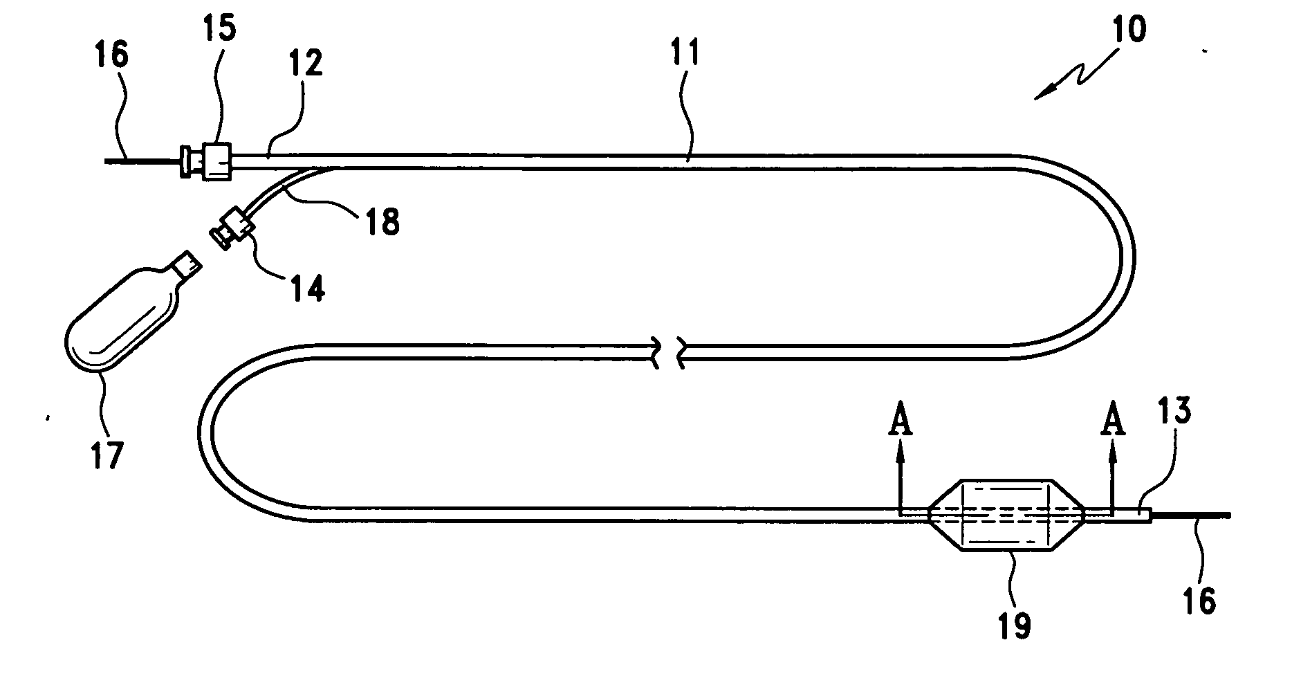
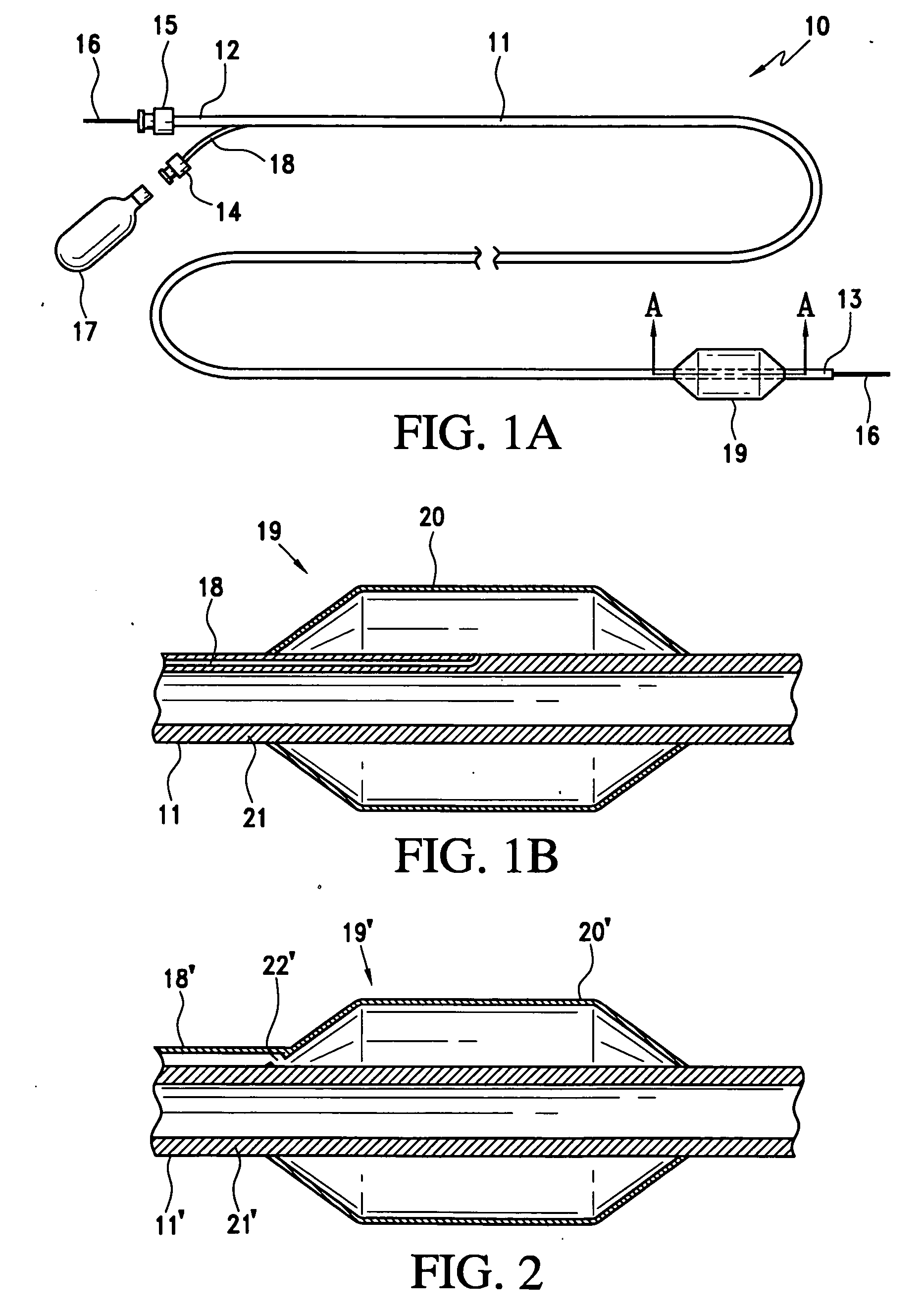
[0032] Referring to FIGS. 1A and 1B, a microcatheter constructed in accordance with the principles of the present invention is described. Microcatheter 10 comprises shaft 11, proximal end 12, distal end 13, inflation port 14, manifold 15, guide wire 16, fluid source 17, inflation lumen 18, and balloon 19.

[0033] Fluid source 17, preferably pressurized gas, such as carbon dioxide (CO2), helium, air, or other fluid, may be attached directly to inflation port 14, or may alternatively pass first through a regulation device to control pressure, flow rate, or other fluid properties. Fluid source 17 is in fluid communication with balloon 19 through inflation lumen 18. Fluid source 17 preferably comprises a CO2 tank having a regulator to control inflation of balloon 19 via inflation port 64.

[0034] In FIG. 1B, balloon 19 comprises flexible member 20 affixed to shaft 11. Inflation lumen 18 passes through wall 21 of shaft 11, so that a distal end of inflation lumen 18 communicates with the sp...


PUM

PropertyMeasurementUnit
Melting pointaaaaaaaaaa
Radiopacityaaaaaaaaaa
aaaaaaaaaa

Abstract

Microcatheters catheters are provided having balloons incorporating radiopaque nanoparticles. Optionally, carbon nanotubes dispersed within the shaft may be configured to react to electrical stimulation, thereby providing a steerable distal end region on the microcatheter. Methods of making the foregoing microcatheters also are provided.

Description

FIELD OF THE INVENTION [0001] The present invention relates generally to microcatheters for performing interventional procedures, such as stenting, in fine vessels. More specifically, the present invention relates to a microcatheter made using nanotechnology. BACKGROUND OF THE INVENTION [0002] Interventional techniques have been developed wherein catheters are used to perform diagnostic and therapeutic procedures, such as stenting and angioplasty. As the medical field becomes increasingly advanced, there is a growing need for precision instruments and devices. In particular, the extension of diagnostic and treatment modalities has been limited by the inability to access smaller vessels, such as those presented by the cerebrovasculature and distal coronary systems. [0003] In particular, the contrast agents typically used to inflate the balloons of balloon catheters are relatively viscous. At smaller catheter sizes, difficulties arise due to the high hydraulic resistance encountered i...

Claims


Application Information

Patent Timeline
IPC IPC(8): A61M29/00A61M25/00A61M31/00A61M37/00A61F2/958
CPCA61L29/126A61L29/18A61L2400/12A61M25/0045A61M25/0158A61M25/10A61M25/1029A61M25/1036A61M2025/0042A61M2025/1079A61M2025/1084
Inventor BATES, MARK C.
Owner NEXEON MEDSYST
Why Eureka
Try Eureka