System and method for synchronization of isochronous data streams over a wireless communication link

a technology of wireless communication and isochronous data, applied in the direction of synchronization arrangement, data switching network, electric controller, etc., can solve the problems of affecting the timing of isochronous data frames, affecting the coordination of timing, and affecting the timing of two devices

Inactive Publication Date: 2007-05-03
FREESCALE SEMICON INC
View PDF4 Cites 20 Cited by
  • Summary
  • Abstract
  • Description
  • Claims
  • Application Information

AI Technical Summary

Problems solved by technology

However, it can be difficult to maintain the timing of these data frames between multiple remote devices over a wireless link since the clock in every device will likely have a slightly different frequency.
And while this slight variation in frequency will not cause problems with internal signal processing, it can be disastrous with respect to coordinated timing.
Over time even slight differences in frequency will cause the timing between two devices to drift.
And once the drift becomes too great, the timing of the...

Method used


Image

  • System and method for synchronization of isochronous data streams over a wireless communication link
  • System and method for synchronization of isochronous data streams over a wireless communication link
  • System and method for synchronization of isochronous data streams over a wireless communication link

Examples


first exemplary embodiment

[0019] In a first exemplary embodiment a time stamp is provided with each data packet sent from a host interface. This time stamp includes a periodic signal identifier (e.g., a beacon number) and a time offset value with respect to that periodic signal identifier.

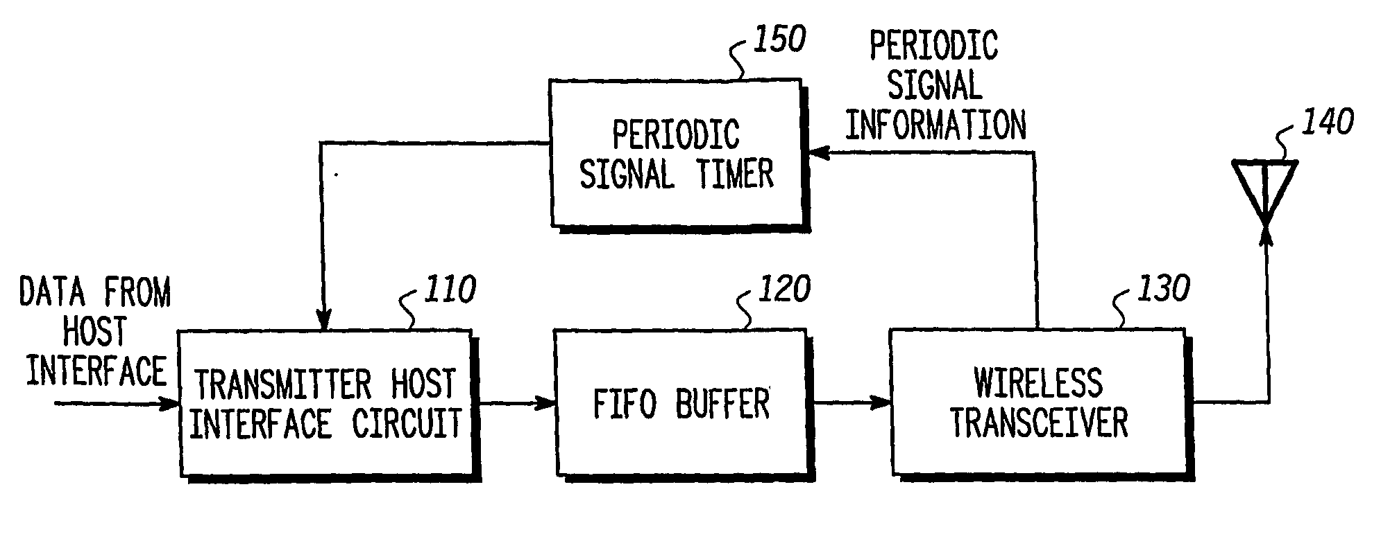
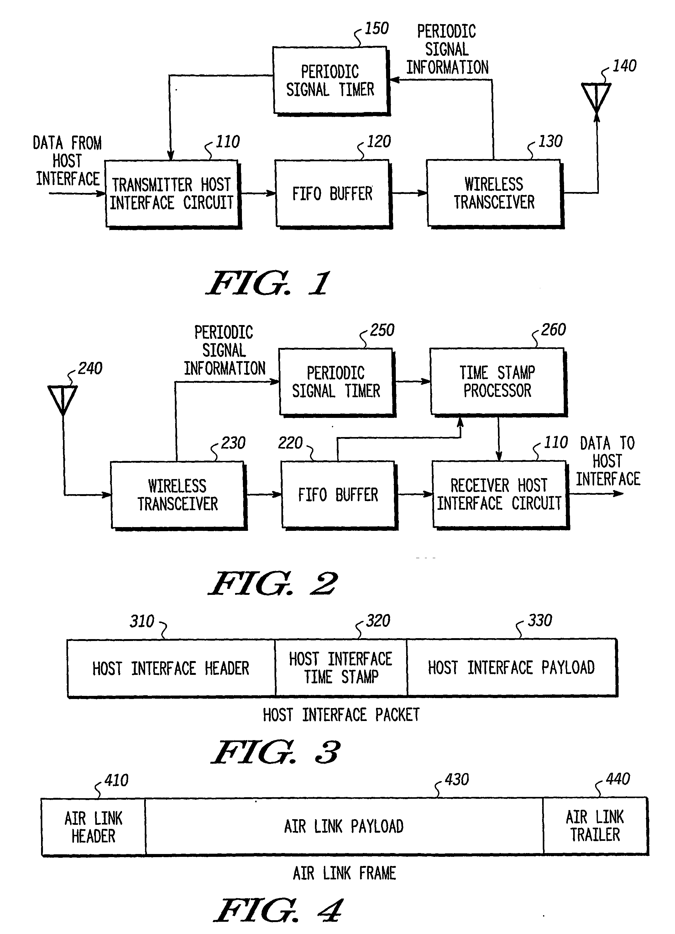
[0020]FIG. 1 is a block diagram of a transmitter device according to the first exemplary embodiment of the present invention. As shown in FIG. 1, the transmitting device 100 includes a transmitter host interface circuit 110, a first-in-first-out (FIFO) buffer 120, a wireless transceiver 130, an antenna 140, and a periodic signal timer 150.

[0021] The transmitter host interface circuit 110 receives host data packets from host circuitry (not shown) in the local transmitter device 100. These host data packets include data from the host in a format that a corresponding host at a remote receiver device could use (e.g. MPEG cells, MPEG cells encapsulated in a 1394 or HSDI format, Ethernet packets, internet protocol packets, PCM ...

second exemplary embodiment

[0065] In a second exemplary embodiment a time stamp is provided with each host interface packet sent from a host interface, and with each air link frame sent from a wireless transceiver. The time stamp for each host interface packet includes a time value taken from a free-running clock at the transmitting device. The time stamp for each air link frame includes a periodic signal identifier (e.g., a beacon number) and a time value from the free-running clock corresponding to that periodic signal identifier.

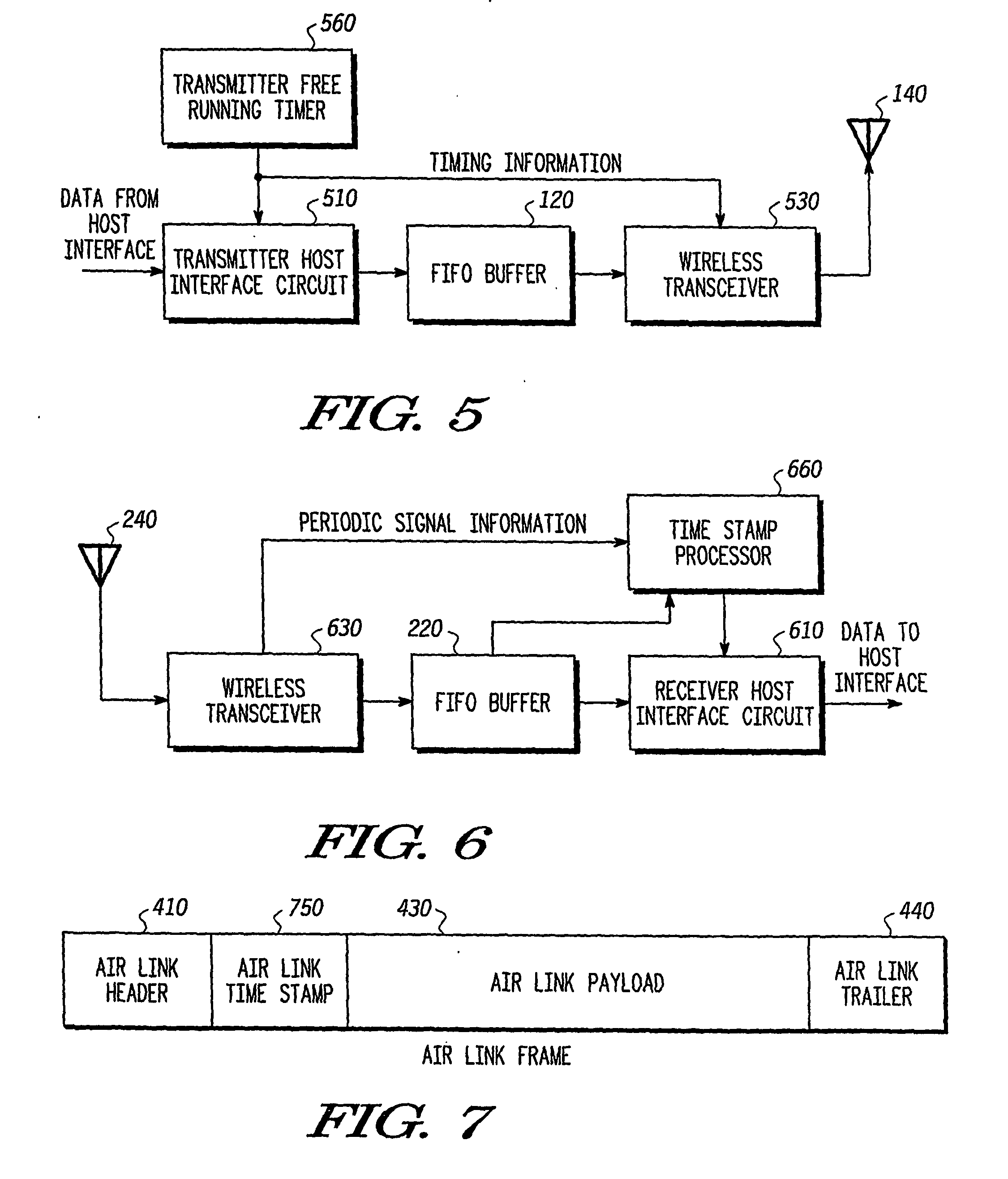
[0066]FIG. 5 is a block diagram of a transmitter device according to the second exemplary embodiment of the present invention. As shown in FIG. 5, the transmitting device 500 includes a transmitter host interface circuit 510, a transmitter FIFO buffer 120, a wireless transceiver 530, an antenna 140, and a transmitter free-running timer 560.

[0067] The transmitter host interface circuit 510 receives host data packets from host circuitry (not shown) in the local transmitter device 5...

third exemplary embodiment

[0106] In a third exemplary embodiment the first and second exemplary embodiments can be merged. In this embodiment a time stamp is provided with each data packet sent from a host interface. Like the first exemplary embodiment, this time stamp includes a periodic signal identifier (e.g., a beacon number) and a time offset value with respect to that periodic signal identifier. However, like the second exemplary embodiment, a free-running clock can be used at the transmitting device to mark the time when each host interface is processed.

[0107] In this embodiment, the host interface packets 300 and the air link frames 400 are as described with respect to the first exemplary embodiment. However, the third exemplary embodiment allows for transmitters that use a free-running clock for time stamping as well as those that use a periodic signal value and offset for time stamping.

[0108] In order to allow these two types of devices to properly communicate, this embodiment requires a transmit...


PUM


Abstract

A transmitter (500) is provided for transmitting host data over a wireless channel. The transmitter (500) includes a free-running timer (560) that provides a series of increasing free-running timing values; a host interface circuit (510) that receives host data from a local host circuit and a first free-running timing value from the series of increasing free-running timing values; a detection circuit (530) for detecting a global synchronizing event and receiving a second free-running timing value from the series of increasing free-running timing values, and for placing the host data and the first free-running timing value into a host interface packet; and a wireless transceiver (530) for adding the second free-running timing value and an identifier for the global synchronizing event to the host interface packet to form an air link frame, and transmitting the air link frame over a wireless channel to a remote wireless device.

Description

CROSS-REFERENCE TO RELATED PATENT DOCUMENTS [0001] This application relies for priority on U.S. provisional application Ser. No. 60 / 483,629, by William M. Shvodian et al., filed Jul. 1, 2003, entitled “SYNCHRONIZATION OF ISOCHRONOUS STREAMS OVER A WIRELESS COMMUNICATIONS LINK.”FIELD OF THE INVENTION [0002] The present invention relates in general to wireless communication systems, such as ultrawide bandwidth (UWB) systems, including mobile transceivers, centralized transceivers, related equipment, and corresponding methods. Another aspect of the present invention relates to a wireless transceiver that can timestamp sensitive data packets with respect to a global synchronizing event such that timing of the data packets can be preserved in an efficient manner. This allows a wireless network to send data to one or more receiving devices in a way that allows the timing relationship of the transmitted packets to be maintained over an extended period of time. BACKGROUND OF THE INVENTION [...

Claims


Application Information

Patent Timeline
IPC IPC(8): G05B11/01H04B1/69H04J3/06H04L7/00H04L12/56
CPCH04B1/7183H04J3/0632H04L7/0091H04W56/00H04W56/009H04L69/28
Inventor SHVODIAN, WILLIAM M.APISDORF, JOEL Z.
Owner FREESCALE SEMICON INC
Why Eureka
Try Eureka