
Apparatus, system, and method for managing response latency

a response latency and response technology, applied in the field can solve the problems of severe degraded communication between the client and the computation module, insufficient computation module processing bandwidth, and insufficient service to the client of the computation module, etc., to achieve the effect of managing response latency

Inactive Publication Date: 2007-05-03
IBM CORP
View PDF28 Cites 14 Cited by
  • Summary
  • Abstract
  • Description
  • Claims
  • Application Information

AI Technical Summary

Benefits of technology

[0019] In one embodiment, the security module may block associating the client to the first blade server in response to the client communicating with the first blade server through an invalid communication module. The system manages the response latency of a client associating with a blade server and guards against an unauthorized client associating with the blade server by checking for communications through invalid communication modules.
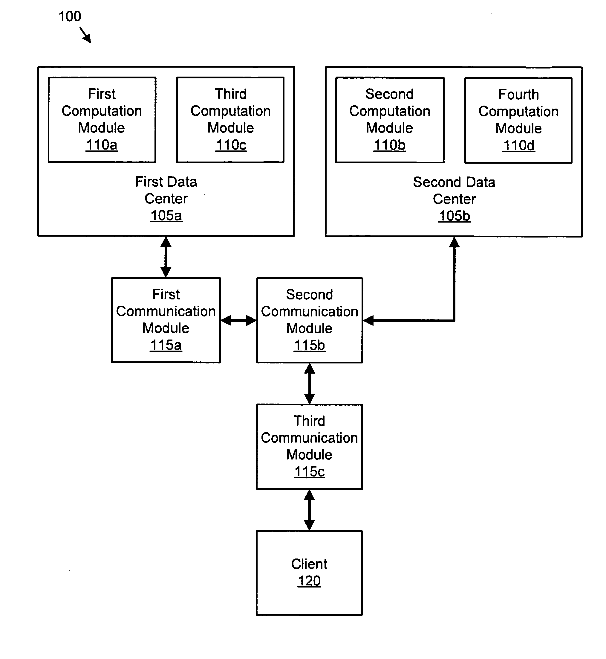
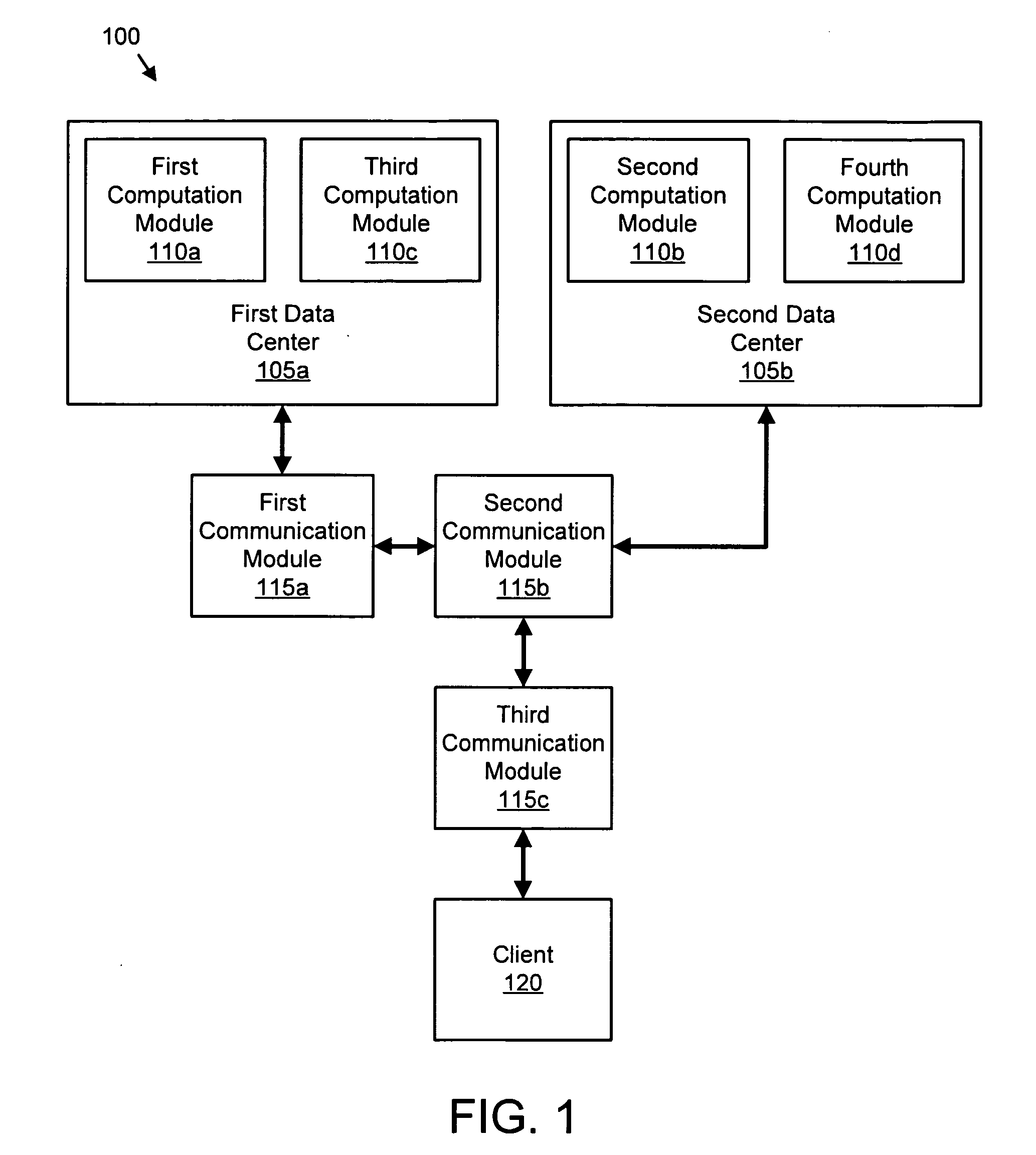
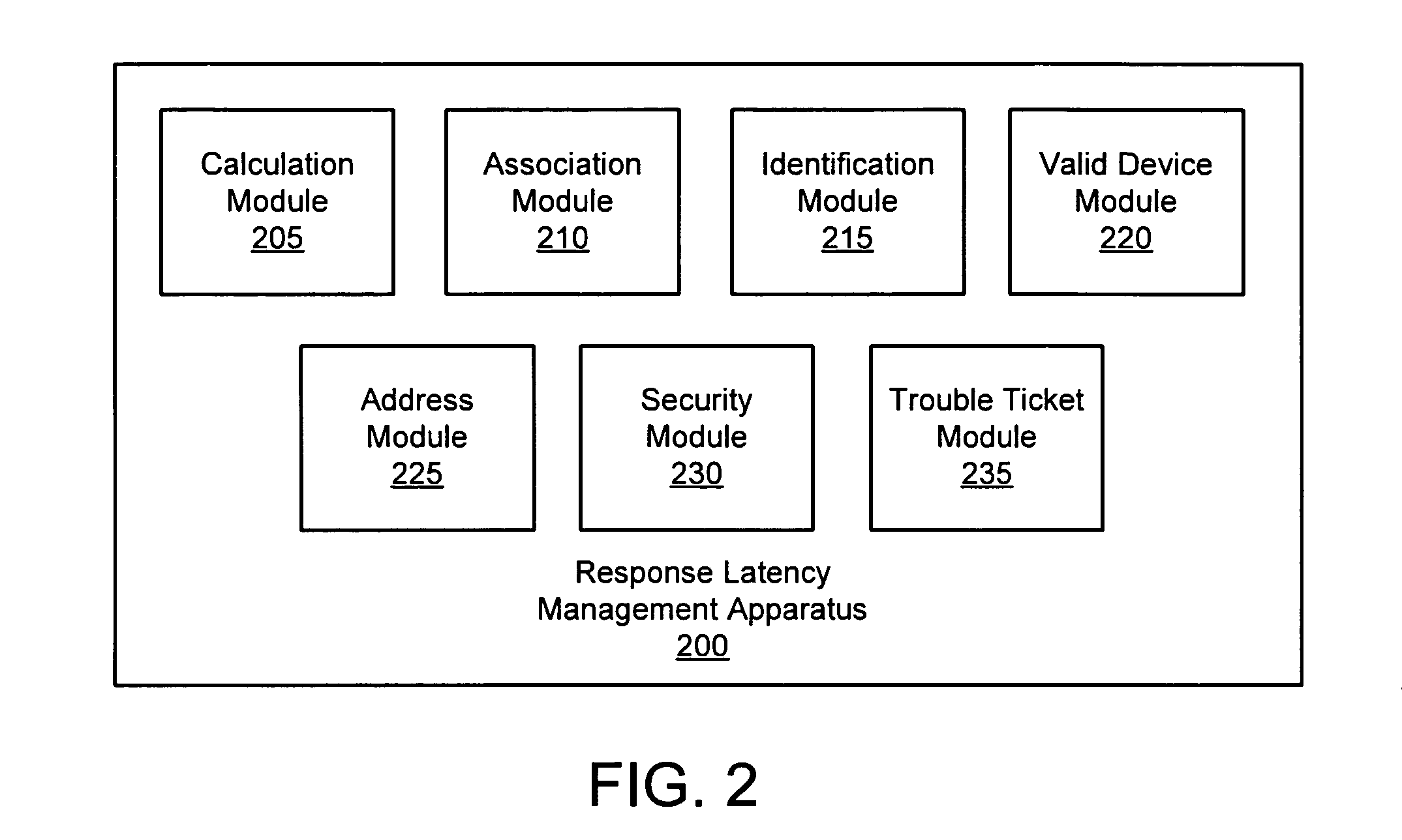
[0021] An identification module identifies a computation module. A calculation module calculates the number of communication modules that transceive a packet between the computation module and a client as a hop count. An association module associates the client with the computation module in response to the hop count satisfying a count range of a response policy. In one embodiment, a trouble ticket module generates a trouble ticket in response to a specified number of clients having a hop count greater than the count range. The method manages the response latency for a client such that the computation module provides acceptable service to the client.

Problems solved by technology

Unfortunately, although the computation module may have sufficient processing bandwidth for the client, the input / output (“I / O”) response latency may still be excessive.
Yet the communications between the computation module and the client may be so delayed by the repeated transceiving of packets by a plurality of communication modules that communications between the client and the computation module are severely degraded.
Thus a computation module with sufficient processing bandwidth may not provide adequate service to a client because of long response latency.
Response latency may be difficult to measure.

Method used


Image

  • Apparatus, system, and method for managing response latency
  • Apparatus, system, and method for managing response latency
  • Apparatus, system, and method for managing response latency

Examples


Embodiment Construction

[0033] Many of the functional units described in this specification have been labeled as modules, in order to more particularly emphasize their implementation independence. For example, a module may be implemented as a hardware circuit comprising custom very large scale integration (“VLSI”) circuits or gate arrays, off-the-shelf semiconductors such as logic chips, transistors, or other discrete components. A module may also be implemented in programmable hardware devices such as field programmable gate arrays, programmable array logic, programmable logic devices or the like.

[0034] Modules may also be implemented in software for execution by various types of processors. An identified module of executable code may, for instance, comprise one or more physical or logical blocks of computer instructions, which may, for instance, be organized as an object, procedure, or function. Nevertheless, the executables of an identified module need not be physically located together, but may compri...


PUM


Abstract

An apparatus, system, and method are disclosed for managing response latency. An identification module identifies a computation module that may communicate with a client through one or more communication modules. A calculation module calculates the number of communication modules that transceive a packet between the computation module and the client as a hop count. An association module associates the client with the first computation module in response to the hop count satisfying a count range of a response policy. In one embodiment, a trouble ticket module generates a trouble ticket in response to a specified number of clients having a hop count greater than the count range.

Description

BACKGROUND OF THE INVENTION [0001] 1. Field of the Invention [0002] This invention relates to managing response latency and more particularly relates to managing response latency when associating a client with a remote computation module. [0003] 2. Description of the Related Art [0004] A data processing device such as a computer workstation, a terminal, a server, a mainframe computer, or the like, herein referred to as a client, may often employ a remote computation module to execute one or more software processes. The computation module may be a server or the like. The server may be configured as a blade server, a modular server with one or more processors, memory, and communication capabilities residing in blade center. The blade center may be an enclosure such as a rack-mounted chassis with a plurality of other blade servers. The blade center may include data storage devices, data storage system interfaces, and communication interfaces. A data center may include a plurality of bl...

Claims


Application Information

Patent Timeline
IPC IPC(8): G06F15/173
CPCH04L41/5074H04L43/0852
Inventor CROMER, DARYL C.LOCKER, HOWARD J.SPRINGFIELD, RANDALL S.WALTERMANN, ROD D.
Owner IBM CORP
Learn More