Distributed impedance sensor

Inactive Publication Date: 2007-05-10
DAVID S NYCE
View PDF8 Cites 11 Cited by
  • Summary
  • Abstract
  • Description
  • Claims
  • Application Information

AI Technical Summary

Benefits of technology

[0017] For example, when measuring the level of a dielectric fluid according to the present invention, the capacitance changes with the level of the fluid. The electronic circuit indicates the level by directly or indirectly measuring the change in capacitance. However, according to a preferred embodiment of the present invention, it is important that the inductive reactance be non-negligible (i.e. it must be more than ten percent of the capacitive reactance). This allows the capacitance to be considered as a multitude of individual capacitances, each separated from the next by a series inductance. This is accomplished by using, for example, a dual helix configuration instead of, for example, an interdigital comb configuration that is commonly used with capacitive sensors.
[0018] In the example above, of a sensor according to the present invention for measuring the level of a dielectric fluid, separating the capacitances by series inductances provides a distributed impedance, whereby both the capacitances and inductances of the sensing element are distributed along the sensing axis. This enables shaping of the electromagnetic field along the sensing element as may be desired for better performance of the sensor. When sensing a dielectric material according to the present invention, the electromagnetic field is shaped so that the electric field penetrates into the measured material, but is concentrated in a volume close to the sensing element in order to avoid sensing unwanted materials that may be nearby. Likewise, when sensing an electrically conductive material, the electromagnetic field is shaped so that the magnetic field penetrates into the measured material, but is concentrated in a volume close to the sensing element in order to avoid sensing unwanted conductive materials that may be nearby.
[0019] According to the present invention, at least two of the conductive members of the sensing element are excited by an alternating current oscillator in an anti-phase mode. This means that a first terminal can be connected to ground, while a second terminal is alternately energized with a positive and then a negative voltage. Alternatively, the first terminal can instead be connected to a first alternating voltage while the second terminal is connected to a second alternating voltage that is not in phase with the voltage of the first terminal. Such anti-phase energizing of the sensing element allows for the measurement of the sensing element AC (alternating current) impedance, and changes in the impedance that are caused by changes in a parameter of the measured variable structure.

Problems solved by technology

Disadvantages of this sensing system, compared to the present invention, include limited resolution, higher electronics cost, and limited sensitivity.
Disadvantages of this sensing system, compared to the present invention, include a very small signal level, resulting in reduced stability when the liquid level is low, and the requirement for a more complicated set of electronics.
When the liquid level is very low, both measured capacitances are very small, and are therefore easily affected by parasitic capacitances and electrical noise.
Another disadvantage of this system is the need for a stationary tank circuit, meaning that once fabricated, the sensor length can not be changed without destroying the tank circuit.
Some disadvantages of this system include the need for highly stable electronics, since the inductance is low, and the fixed sensing length, which cannot be easily changed once the sensing element has been fabricated.

Method used


Image

  • Distributed impedance sensor
  • Distributed impedance sensor
  • Distributed impedance sensor

Examples


Embodiment Construction

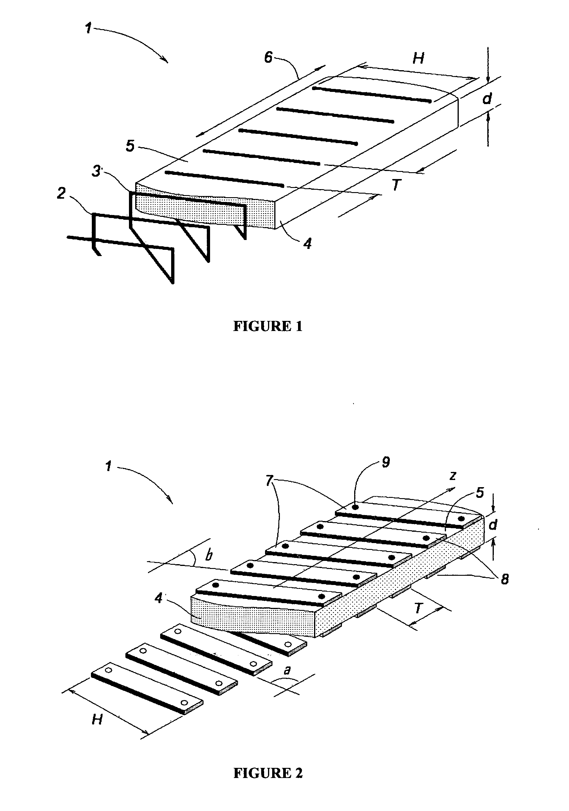
[0035] Prior art non-contact sensors using an electromagnetic field to determine fluid level or the position of a conductive or dielectric target have suffered from high manufacturing cost or low performance. The present invention overcomes these problems by utilizing a novel set of technical advancements that can be used together or independently. A first embodiment of the present invention is shown in FIG. 1, in which two conductors 2, 3, are shaped as a double helix, also called a bifilar helix. This provides an improvement over the well known configuration of interdigital combs of prior art that is commonly used in capacitive sensors. In prior art interdigital comb configurations, it is desirable to maximize the starting capacitance between the two (or more) conductor plates that form the capacitance. The starting capacitance is maximized by making the areas of the plates as large as is practical for a given sensor size. The plate size, and capacitance, is maximized by reducing ...


PUM


Abstract

An apparatus is disclosed for measuring one or more parameters of a variable physical structure, at least one of the parameters being fluid level, position, velocity or acceleration. The apparatus includes an electromagnetic sensing element comprising at least two electrically conductive members that are electrically insulated from one another. A distributed capacitance and a distributed inductance are each formed along a length of the sensing element. The inductive reactance is at least ten percent of the capacitive reactance, thereby allowing the capacitance to be distributed, rather than acting as a “lump capacitance”. The distributed capacitance enables shaping of the electric and magnetic fields around the electromagnetic sensing element so that disturbance by nearby electromagnetic fields, conductors, and dielectrics is minimized. When the apparatus is configured as a fluid level sensor, the capacitance is affected by the permittivity and the level of the measured fluid. A reference sensor can be used to compensate for changes in the permittivity of the fluid. When the apparatus is configured as a position sensor, the capacitance and / or inductance are affected by the position of an electrically conductive or dielectric target. The position measurement can be differentiated to obtain measurements of velocity or acceleration. Electronic circuits for operating the sensing element are also shown.

Description

BACKGROUND OF THE INVENTION [0001] 1. Field of the Invention [0002] The present invention relates to sensors for measuring a parameter of a variable physical structure. The variable structure may include a fluid within a vessel, or it may include a movable solid target. More specifically, the present invention relates to sensors that measure the parameter through the use of an electromagnetic field that is disposed in a volume that includes the variable structure. In the case of a fluid variable structure, the parameter is measured and utilized to determine a fluid level. In the case of a solid target, the parameter is measured and utilized to determine a position, velocity, or acceleration of the target as the target moves along a sensing axis. [0003] 2. Description of the Prior Art [0004] According to the present invention, a fluid level can be measured through the application of an electromagnetic field, without the use of a float. The present invention also teaches the measureme...

Claims


Application Information

Patent Timeline
IPC IPC(8): G01F23/26G08B21/00
CPCG01F23/68G01P3/50G01D5/243G01D5/202G01D5/2405G01P15/16G01F23/263
Inventor NYCE, DAVID SCOTTPCHELNIKOV, YURIY NIKITICH
Owner DAVID S NYCE
Why Eureka
Try Eureka