Vehicle collision detecting device

a detection device and vehicle technology, applied in the direction of vehicular safety arrangements, pedestrian/occupant safety arrangements, tractors, etc., can solve the problems of difficult to know which collision and wire breakage takes pla

Inactive Publication Date: 2007-05-10
DENSO CORP
View PDF15 Cites 32 Cited by
  • Summary
  • Abstract
  • Description
  • Claims
  • Application Information

AI Technical Summary

Benefits of technology

[0008] Another object of the invention is to provide a capacitor type collision detecting device of a

Problems solved by technology

If the connection between the capacitance detecting circuit and the collision detecting device breaks down in the disclosed collision detectin

Method used


Image

  • Vehicle collision detecting device
  • Vehicle collision detecting device
  • Vehicle collision detecting device

Examples


first embodiment

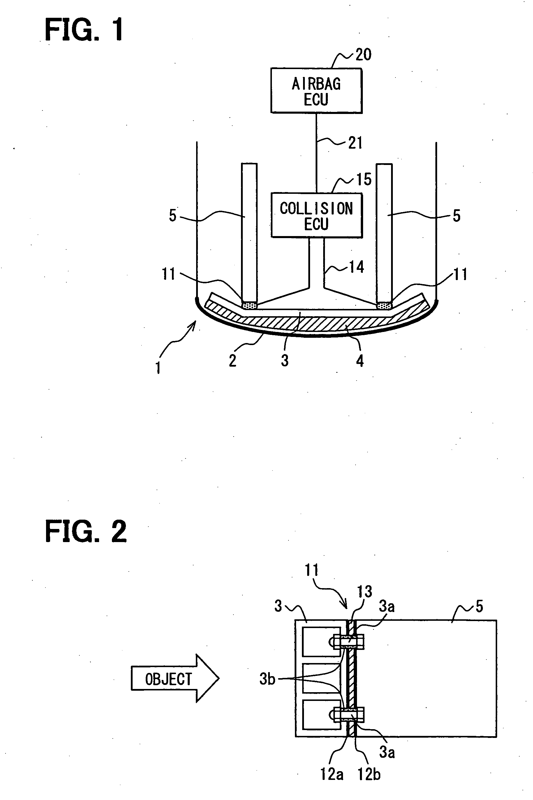
[0024] A vehicle collision detecting device according to the invention will be described with reference to FIGS. 1-7A and 7B.

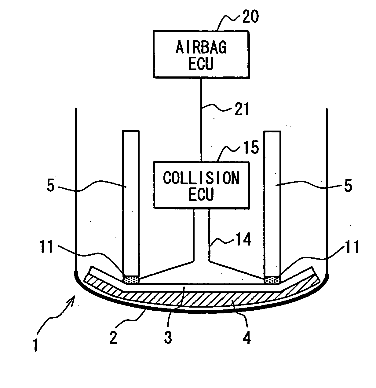
[0025] The vehicle collision detecting device includes a pair of sensors 11 and a collision detecting ECU 15, which is connected by a wire 21 to an airbag ECU 20. The sensors 11 and the collision detecting ECU 15 are connected by lead wires 14. The sensors 11 may be directly connected to the airbag ECU 20 if the collision detecting ECU 15 is included in the airbag ECU 20.

[0026] The sensors 11 are mounted in the front bumper 1 of a vehicle. Of course, the sensor 11 may be mounted in a rear bumper or side bumpers. The bumper 1 includes a bumper cover 2, a bumper reinforcement 3, an absorber 4, a pair of side members 5, etc. The bumper cover 2 is made of a resin such as polypropylene and extends laterally from one side of the vehicle to the other to cover the bumper reinforcement 3 and the absorber 4. The bumper reinforcement 3 is a metal beam that extends along...

second embodiment

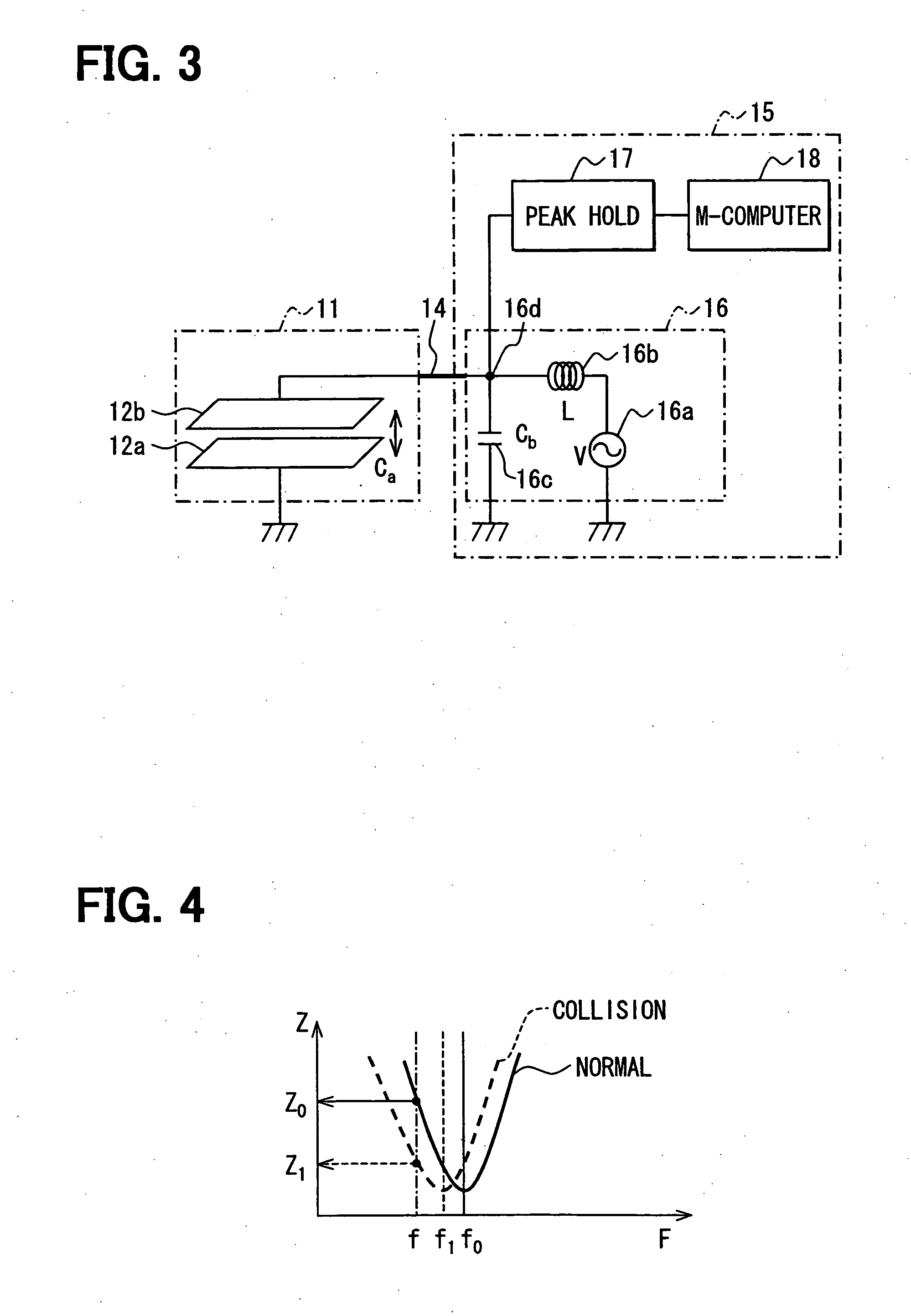
[0036] The driving circuit 16 of the collision detecting device includes a coil 16b connected in parallel with the sensor 11 and a diagnostic capacitor 16c connected in series with the sensor 11, the oscillator 16a and the coil 16b.

[0037] If a collision takes place, the sensor 11 is crushed to increase the capacitance Ca. Accordingly, the resonant frequency becomes lower than the normal resonant frequency, and the impedance of the resonant circuit lowers. Accordingly, the peak voltage at the joint 16d lowers in the same manner as the first embodiment. If the lead wire 14 breaks down between the sensor 11 and the driving circuit 16, the capacitance Ca of the L-C resonant circuit drops out. Accordingly, the resonant frequency becomes higher than the normal resonant frequency, and the impedance of the resonant circuit increases. Accordingly, the peak voltage at the joint 16d increases in the same manner as the first embodiment.


PUM


Abstract

A vehicle collision detecting device includes a capacitor type sensor mounted on a portion of the vehicle, a resonant circuit connected to the sensor by a lead wire and a microcomputer for judging a collision with an object and a breakdown of the lead wire. The sensor has a pair of plate electrodes and a dielectric member disposed between the electrodes so that its capacitance changes if the sensor is crushed. The resonant circuit is constituted of an oscillator generating an ac signal of a fixed frequency, a coil and a diagnostic capacitor. The microcomputer judges which of collision and wire breakdown takes place based on the voltage appears on the lead wire when the oscillator generates the signal of a fixed frequency.

Description

CROSS REFERENCE TO RELATED APPLICATION [0001] The present application is based on and claims priority from Japanese Patent Applications: 2005-325095, filed Nov. 9, 2005 and 2006-235903, filed Aug. 31, 2006, the contents of which are incorporated herein by reference. BACKGROUND OF THE INVENTION [0002] 1. Field of the Invention [0003] The present invention relates to a collision detecting device for detecting a collision with an object or a pedestrian at a portion of a vehicle that deforms when the collision takes place. [0004] 2. Description of the Related Art [0005] In order to protect a pedestrian, it has been proposed. that a collision detecting device is mounted on a bumper of a vehicle to actuate a pedestrian protecting device such as an air bag. JP-A-2000-177514 or U.S. Pat. No. 6,561,301 B1, a counterpart U.S. patent, proposes a capacitor type collision detecting device that has a capacitor fixed to a surface portion of the bumper. The capacitor has a pair of electrodes and an...

Claims


Application Information

Patent Timeline
IPC IPC(8): B60K28/10B60Q1/00
CPCB60R19/483B60R21/0136B60R2021/01184
Inventor KIRIBAYASHI, SHINICHI
Owner DENSO CORP
Why Eureka
Try Eureka