
Electric power steering device

a technology of electric power steering and steering wheel, which is applied in the direction of gearing details, gearing, transportation and packaging, etc., can solve the problems of large steering load, and deterioration of steering feeling, so as to prevent plastic deformation of cylindrical elastic bodies and improve durability.

Inactive Publication Date: 2007-05-10
JTEKT CORP
View PDF8 Cites 61 Cited by
  • Summary
  • Abstract
  • Description
  • Claims
  • Application Information

AI Technical Summary

Benefits of technology

[0019] In view of the above-mentioned circumstances, it is a main object of the present invention to provide an electric power steering device capable of being provided with limiting members for limiting the deflection amounts of circular elastic bodies (for example, belleville springs) without increasing the size of a small gear portion (for example, a worm).
[0020] Furthermore, in addition to the above-mentioned object, it is another object of the present invention to provide an electric power steering device capable of raising the durability of elastic bodies for reducing the steering load in a steering range wherein a steering-assisting electric motor is not driven and also capable of not increasing the backlash amount at the meshing portion of gears even in the case where the abrasion amounts of the teeth of the gears increase.
[0021] Moreover, in addition to the above-mentioned objects, it is still another object of the present invention to provide an electric power steering device capable of preventing the plastic deformation of elastic bodies for reducing the steering load in a steering range wherein a steering-assisting electric motor is not driven, capable of raising the durability thereof, and capable of eliminating the necessity of reassembling the elastic bodies.

Problems solved by technology

Hence, in the case where the device is configured that, when the steering wheel is steered left or right from the steering neutral position, steering assistance is carried out by the rotation of the electric motor in the early stage of the start of the steering, the steering assistance is carried out even if the steering angle of a vehicle running at high speed is a small angle of approximately one degree, for example; hence, steering feeling is deteriorated.
As a result, the load for rotating the driving shaft of the electric motor is applied reversely to the steering wheel via the worm, the worm wheel, the output shaft, the torsion bar and the input shaft; hence, the steering load becomes large and steering feeling is deteriorated.
However, in the configuration of the electric power steering device disclosed in Japanese Patent Application Laid-Open No. 11-43062 (1999) described above, in the case where the force applied to the worm in the axial direction is relatively large while the steering is performed in the range wherein the electric motor is not driven, the forces applied to the belleville springs may exceed the deflection limits thereof.
In such a case, the belleville springs may undergo plastic deformation and become nonfunctional, or the lowering of the durability thereof may be caused.
However, this kind of configuration causes a problem of increasing the backlash amount at the meshing portion owing to the abrasion of the teeth of the worm and the worm wheel.
Still further, the difference in the dimensions of the inner fringe and the outer fringe of the belleville spring is relatively large; hence, this also causes the problem of inevitably increasing the size of the worm portion.

Method used


Image

  • Electric power steering device
  • Electric power steering device
  • Electric power steering device

Examples


embodiment 1

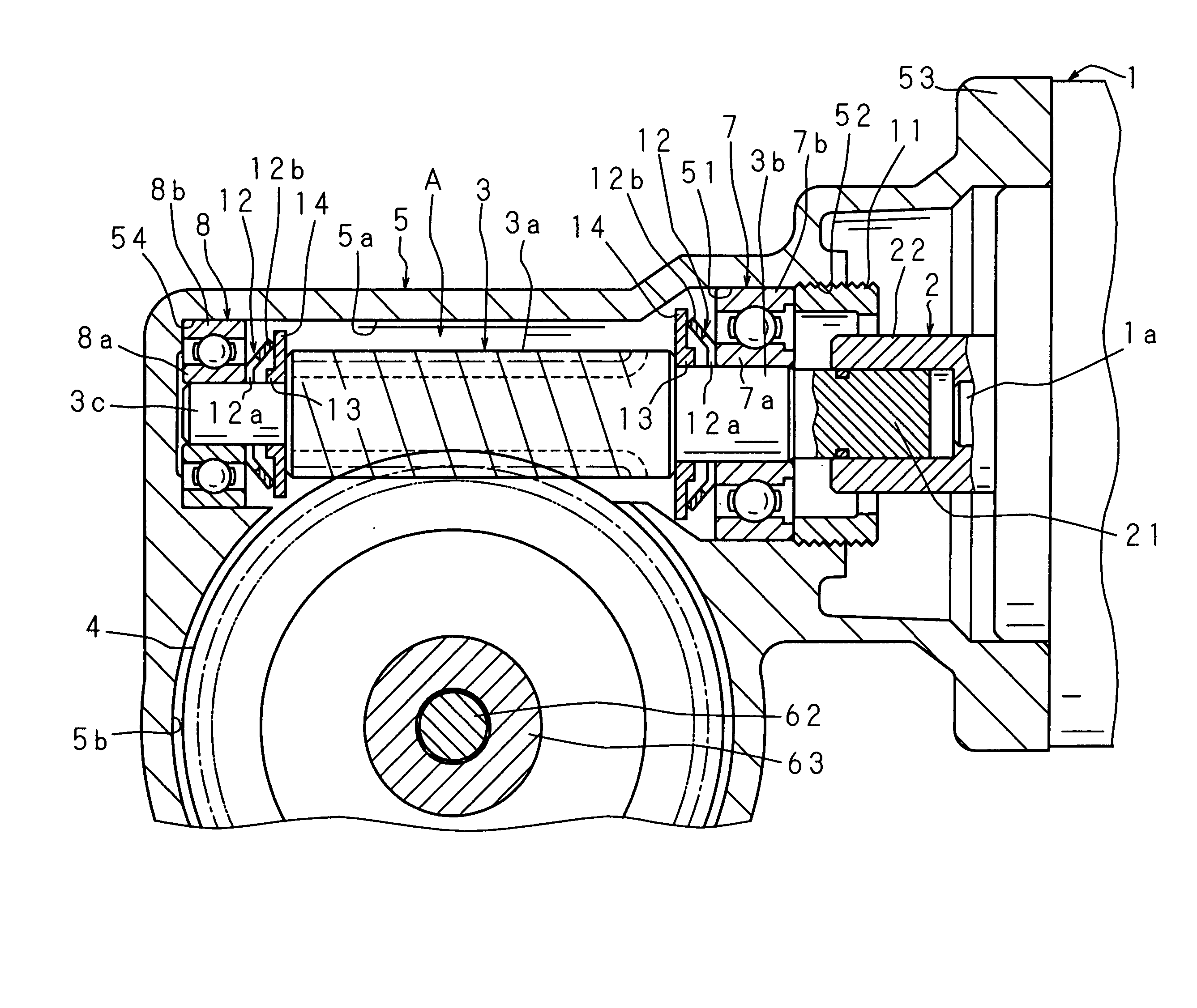
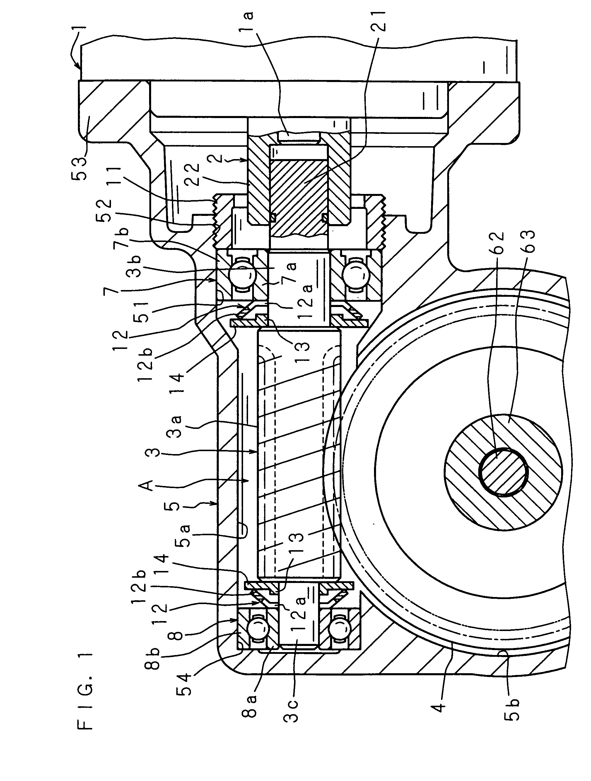
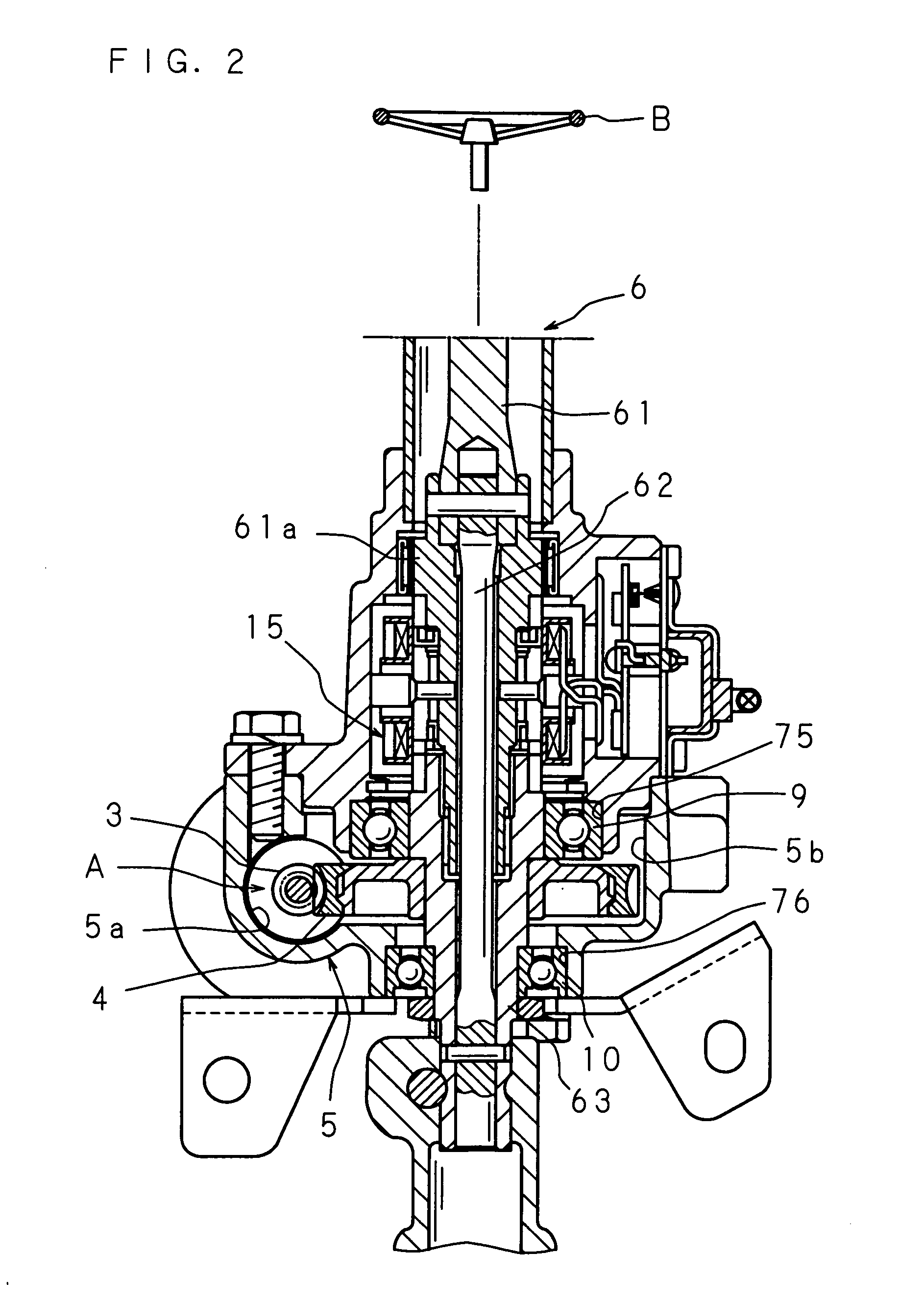
[0065]FIG. 1 is a schematic enlarged sectional view of a reduction gear mechanism portion, showing the configuration of Embodiment 1 of an electric power steering device in accordance with the present invention, and FIG. 2 is a schematic sectional view showing the overall configuration of the electric power steering device in accordance with the present invention.

[0066] The electric power steering device comprises an electric motor 1 for assisting steering, a reduction gear mechanism A, a housing 5 serving as a supporting member for incorporating and supporting the reduction gear mechanism A, and a steering means 6 connected to the reduction gear mechanism A. The reduction gear mechanism A has a worm 3 serving as a small gear connected to the output shaft la of the electric motor 1 via a shaft coupling 2 having a male joint portion 21 and a female joint portion 22, and a worm wheel 4 serving as a large gear meshing with this worm 3.

[0067] The steering means 6 comprises a first ste...

embodiment 2

[0087]FIG. 5 is a schematic enlarged sectional view of a reduction gear mechanism portion, showing the configuration of Embodiment 2 of the electric power steering device in accordance with the present invention.

[0088] Embodiment 2 of the electric power steering device in accordance with the present invention is configured that, instead of the belleville springs 12 and 12, elastic circular bodies 16 and 16 capable of suppressing the movement of the worm 3 in the axial direction and capable of pushing the worm 3 toward the worm wheel 4 are provided. The worm 3 is rotatably supported on the housing 5 via the roller bearings 7 and 8 and the elastic circular bodies 16 and 16.

[0089] The elastic circular bodies 16 and 16 are externally fitted on the outer rings 7b and 8b of the roller bearings 7 and 8, respectively, and configured in a nearly L-shape in cross section so as to have first circular portions 16a and 16a for pushing the worm 3 toward the worm wheel 4 and second circular port...

embodiment 3

[0096] Next, Embodiment 3 of the electric power steering device in accordance with the present invention will be described below. FIG. 6 is a schematic enlarged sectional view of a reduction gear mechanism portion, showing the configuration of Embodiment 3 of the electric power steering device in accordance with the present invention, and FIG. 7 is a schematic enlarged sectional view taken on line VII-VII of FIG. 6.

[0097] In Embodiment 3 of the electric power steering device in accordance with the present invention, the supporting hole 54, provided in the other end portion of the first housing portion 5a of the housing 5, for supporting the roller bearing 8 is configured into an elliptic shape that is made eccentric in a direction wherein the distance H between the rotational centers of the worm 3 and the worm wheel 4 becomes long or short. Hence, the roller bearing 8 can be moved in the direction wherein the distance H between the rotational centers of the worm 3 and the worm whee...


PUM


Abstract

An electric power steering device provided with two belleville springs for suppressing the axial movement of a worm rotated by a steering-assisting electric motor and having shaft portions at its both end portions, and limiting members for limiting the deflection amounts of the two belleville springs. The limiting members are respectively disposed at portions along the outer circumferences of the shaft portions at both end portions of the worm, the respective inner circumferential portions of the two belleville springs are formed into flat portions, the outer circumferential portions thereof are respectively formed into tapered portions having a taper shape, and the limiting members are made contact with the flat portions, thereby limiting the deflection amounts of the tapered portions. Hence, the limiting members can be provided without increasing the size of the worm serving as a small gear.

Description

CROSS-REFERENCE TO RELATED APPLICATIONS [0001] This application is the national phase under 35 U.S.C. §371 of PCT International Application No. PCT / JP2004 / 005522 which has an International filling date of Apr. 16, 2004 and designated the United States of America.BACKGROUND OF THE INVENTION [0002] 1. Field of the Invention [0003] The present invention relates to an electric power steering device that uses an electric motor as a source for generating a steering assistance force. [0004] 2. Description of Related Art [0005] As electric power steering devices for vehicles, a device having the configuration disclosed in Japanese Patent Application Laid-Open No. 2002-21943, for example, is general. This electric power steering device is configured to detect the steering torque applied to the input shaft depending on the relative angular displacement amount between the input shaft connected to the steering wheel and the output shaft coaxially connected to the input shaft via a torsion bar a...

Claims


Application Information

Patent Timeline
IPC IPC(8): B62D5/04F16C25/08F16H1/16H02K7/08
CPCB62D5/0409F16C25/08F16H1/16H02K7/081F16H2057/0213F16C2361/61F16H55/24F16C2380/27
Inventor SHIINA, AKIHIKOSHINTO, HIROAKIMINAMI, MITSUHARUOKAWA, NORITAKESAKUDA, MASAYOSHI
Owner JTEKT CORP
Features
  • Generate Ideas
  • Intellectual Property
  • Life Sciences
  • Materials
  • Tech Scout
  • Unparalleled Data Quality
  • Higher Quality Content
  • 60% Fewer Hallucinations
Learn More