Collapsible stand for machine

a technology of collapsible stand and machine, which is applied in the direction of folding cycle, car/perambulator with multiple axes, manufacturing tools, etc., can solve the problems of complicated and inconvenient folding stand, complicated and inconvenient user, further danger, etc., to achieve convenient and easy spread, easy spread or fold, and smooth and stable lowering of the platform and the machine supported on the platform

Inactive Publication Date: 2007-05-10
REXON IND CORP LTD
View PDF39 Cites 14 Cited by
  • Summary
  • Abstract
  • Description
  • Claims
  • Application Information

AI Technical Summary

Benefits of technology

[0007] The present invention has been accomplished under the circumstances in view. It is therefore one objective of the present invention to provide a collapsible stand that can be conveniently and easily spread for use and folded for carry and / or storage.
[0008] To achieve this objective of the present invention, the collapsible stand provided by the present invention comprises a platform for supporting thereon a machine, two first legs, two second legs, at least one first springy member and a locking means. The platform has two sleeves pivotally connected thereon. The two first legs each have a top end pivotally connected to the platform. Each second leg is pivotally connected to each first leg at a pivotal point and has a top part inserted through the sleeve and slidable along the sleeve resulting in relative movement to the platform. The first springy member is sleeved onto one of the second leg, located between the sleeve and the pivotal point, and stopped against the sleeve. The locking means is connected to the platform for fixing the second legs after spreading the stand such that the first legs and second legs support the platform at a predetermined height. The top parts of the second legs are protruded out of the platform and the first springy member is compressed after the locking means releases the second legs and then the stand is folded.
[0009] By means of the locking means, the two second legs can be conveniently locked relative to the platform after the stand is spread and released from the lock when the user wants to fold the stand. By means of the assembly of the locking means, the two sleeves and the two pairs of the first leg and the interconnected second leg, the user can easily spread or fold the collapsible stand without turning over it. Further, when the user folds the stand, the springy member provides a damping resistance to the platform to help the user smoothly and stably lower the platform and the machine supported on the platform. Furthermore, when the stand is spread, the springy member provides a rebound force to the platform, thereby enabling the user to lift the platform and the machine with less effort. In a preferred embodiment of the present invention, the springy member is a spring so as to save the manufacturing cost of the stand. In addition, after the stand is spread, the stand is steady supported on the floor by the stable structure thereof. Thereby, the present invention improves the disadvantages of the prior arts.

Problems solved by technology

This way, turning and then folding stand 80, is complicated and inconvenient.
Moreover, the user is not easy and further in danger to turn the table saw 82 and the platform 81 from horizontal to vertical by himself because of the heavy weight of table saw 82 and the stand 80.
However, it is expensive to use the gas spring 91 and the piston rod 92 to produce a damping resistance.
However, this pivotal connection with the wheels 94 and the bottom ends of two legs 93 is not stable.

Method used


Image

  • Collapsible stand for machine
  • Collapsible stand for machine
  • Collapsible stand for machine

Examples


Embodiment Construction

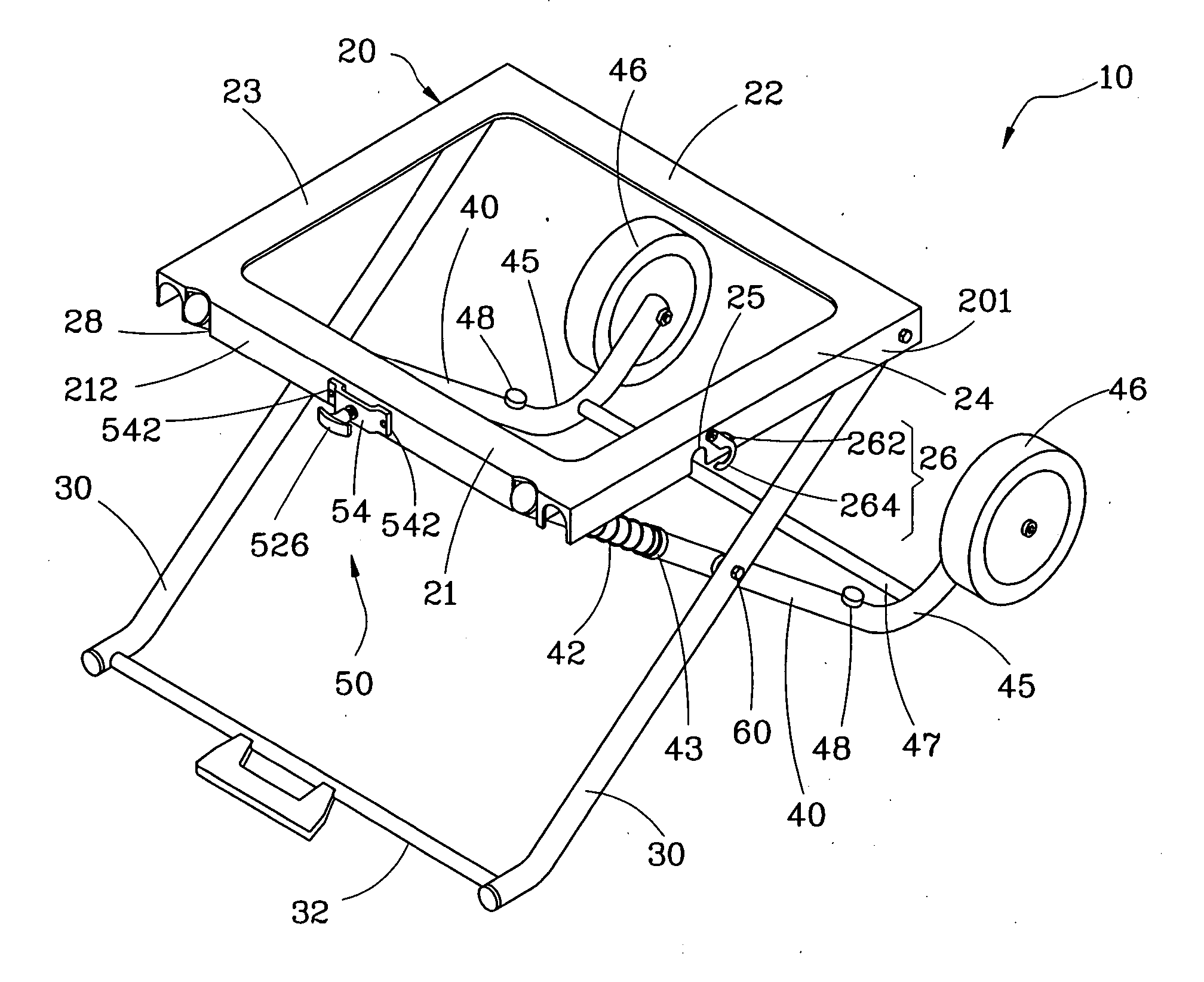
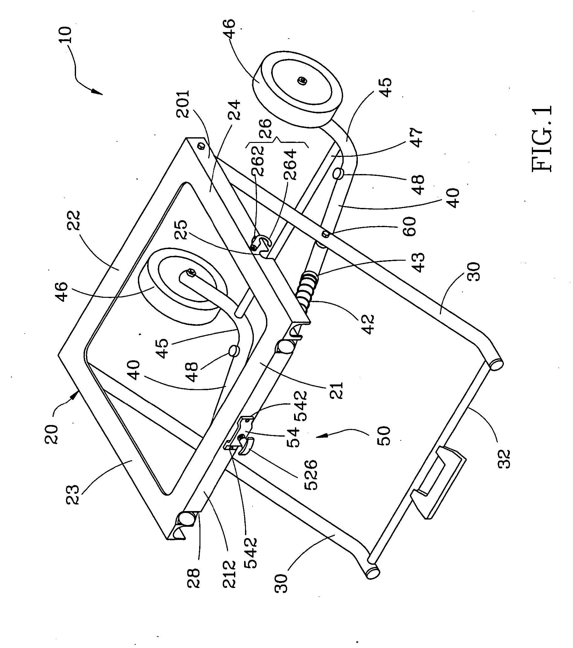
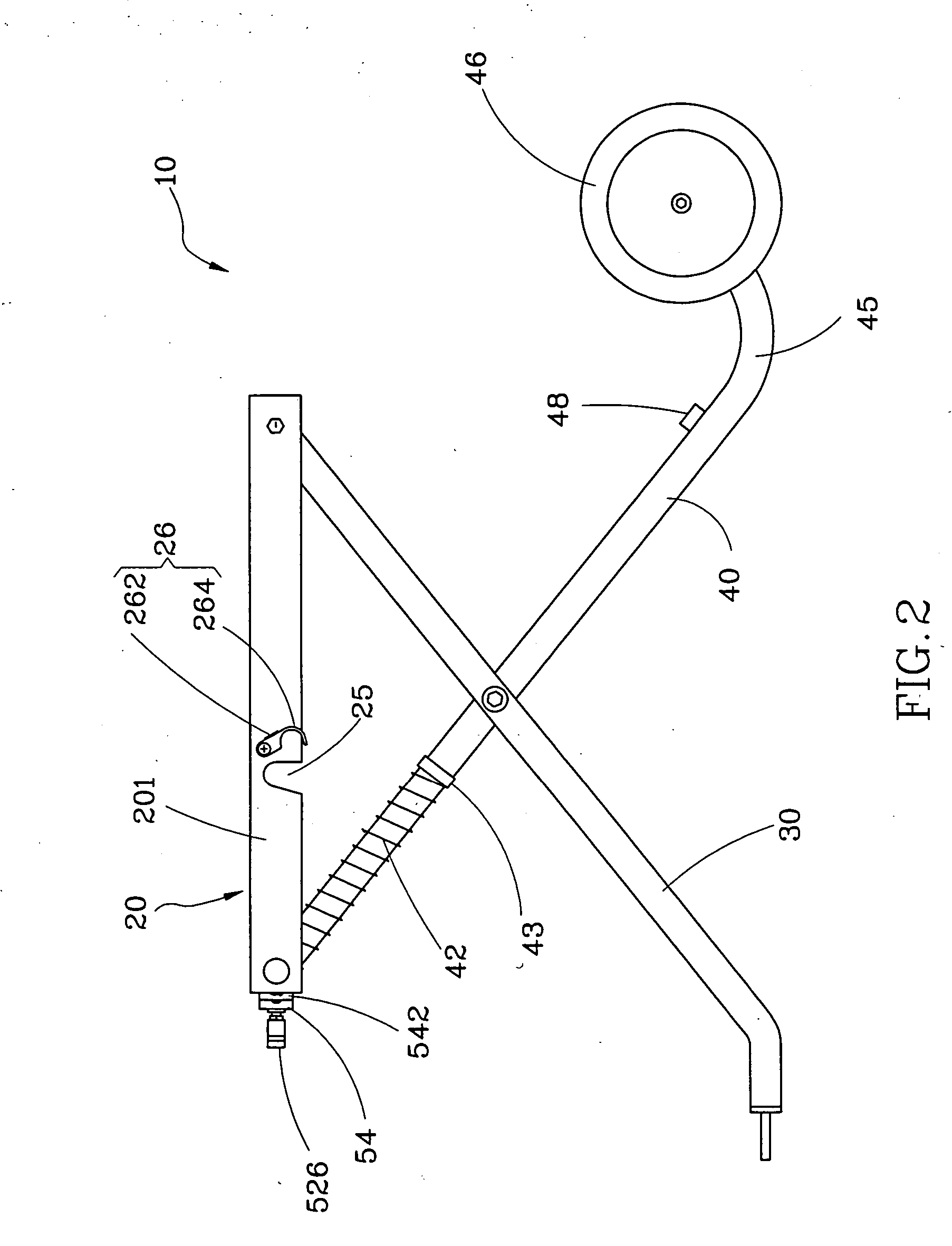
[0022] As shown in FIGS. 1 and 2, a collapsible stand 10 in accordance with a first preferred embodiment of the present invention has a platform 20, two first legs 30, two second legs 40, two first springy members 42, and a locking device 50.

[0023] The platform 20 is adapted to carry a machine (not shown), such as a wood working machine (e.g., table saw, miter saw, scroll saw, band saw, drill press, sander, etc.). The platform 20 can be a plate or frame. According to this embodiment, the platform 20 is a rectangular frame, having a front frame part 21, a rear frame part 22, a left frame part 23, and a right frame part 24. An outside wall 201 of each of the left frame part 23 and the right frame part 24 has an arched notch 25. Two swivel hooks 26 are respectively pivotally mounted to the outside walls 201 of the left frame part 23 and the right frame part 24 adjacent to the arched notches 25. Each of the swivel hooks 26 has a hooked portion 264 pivotally connected to the outside wal...


PUM


Abstract

A folding framework for the cutter includes two opposite and symmetric brackets. Each of the brackets has a first crossed rack and a second crossed rack, that connect across and swing at their intersections. Two limiters mounting at the intersections and crutching between the crossed racks are used to limit the spreading angle of the crossed racks. Each of the first and the second crossed racks has a upper slide-bar and a lower stock. The distance of sliding telescopically of the upper slide-bars in the lower stocks is controlled by a particular device. When the brackets fold crosswise and the upper slide-bars slide into the lower stocks respectively, the mass of the folding framework would be minimums. That would save the holding space for the folding framework.

Description

BACKGROUND OF THE INVENTION [0001] 1. Field of the Invention [0002] The present invention relates to a collapsible stand for supporting a machine, and more particularly the collapsible stand can easily and conveniently be spread for use and folded for carry and / or storage. [0003] 2. Description of the Related Art [0004] An U.S. Pat. No. 6,942,229B2, discloses a collapsible stand for a bench-top power tool. In the patent, as shown in FIGS. 10 and 11, the stand 80 includes a platform 81 on which a table saw 82 is mounted, two first legs 83 pivotally connected to the bottom side of the platform 81, two second legs 84 respectively connected to the two first legs 83 with a crossed manner, and two wheels 85 bilaterally connected to the front part of the platform 81. When wanting to move the table saw 82, the user must turn the table saw 82 and the platform 81 from horizontal to vertical to have the front side of the table saw touch the floor, and then fold the first legs 83 and the second...

Claims


Application Information

Patent Timeline
Patent Type & Authority Applications(United States)
IPC IPC(8): B62B3/02
CPCB25H1/04
Inventor CHIU, CHENG-HUNG
Owner REXON IND CORP LTD
Why Eureka
Try Eureka