Control unit for elctric power steering apparatus

a control unit and electric power steering technology, applied in the direction of electric generator control, dynamo-electric converter control, dynamo-electric gear control, etc., can solve the problems of large noise generated by the motor, short power of the motor, and noise in the vehicle, so as to improve the steering feel of the wheel and reduce the noise of the motor

Active Publication Date: 2007-05-10
NSK LTD +1
View PDF2 Cites 15 Cited by
  • Summary
  • Abstract
  • Description
  • Claims
  • Application Information

AI Technical Summary

Benefits of technology

[0016] The present invention is made by taking the circumstances mentioned above, and an object of the present invention is to provide a control unit for electric power

Problems solved by technology

In the case of steering the steering wheel at a high speed, a power of the motor runs short.
On the other hand, there is a problem that the greater the d-axis current Id affecting the field current is, the larger the noise generated by the motor is.
In this case, the noise in the vehicle is caused by a noise generated

Method used


Image

  • Control unit for elctric power steering apparatus
  • Control unit for elctric power steering apparatus
  • Control unit for elctric power steering apparatus

Examples


embodiment 1

[Embodiment 1]

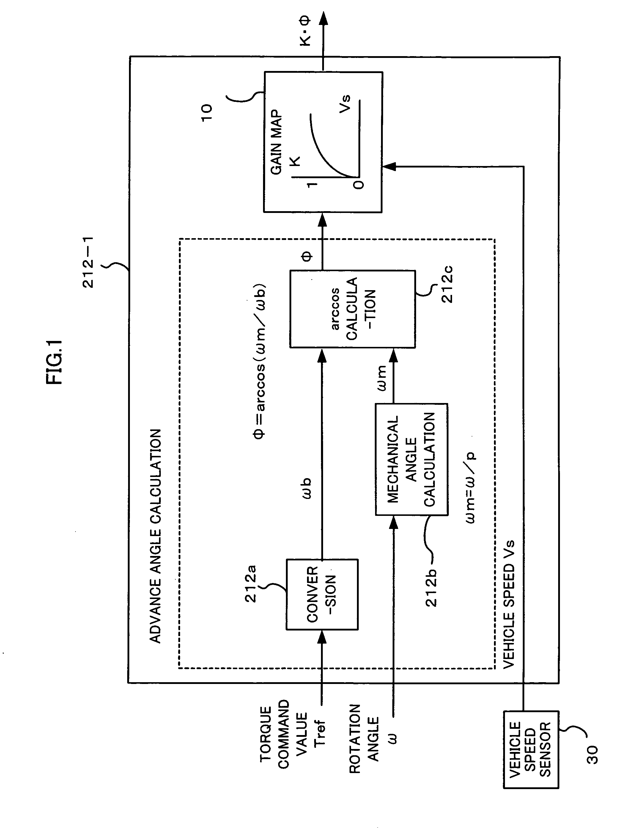
[0031]FIG. 1 shows an embodiment using the present invention, which corresponds to an embodiment using an angle K·φ (corresponding to a new field current command value for weakening a magnetic field) freshly calculated by multiplying an angle φ (corresponding to a field current command value for weakening the magnetic field) by a vehicle speed sensitive gain K (hereinafter, referred to as a gain K) in correspondence to a vehicle speedVs detected by a vehicle speed sensor 30. Aadvance angle calculating portion 212-1 according to the present invention is replaced by a advance angle calculating portion 212 in FIG. 9, and is applied to a control block diagram in FIG. 8. A difference between the advance angle calculating portion 212-1 and the conventional advance angle calculating portion 212 exists in that a gain map 10 having the angle φ corresponding to an output of an arcCOS calculating portion 212c of the advance angle calculating portion 212 and a vehicle speed Vs cor...

embodiment 2

[Embodiment 2]

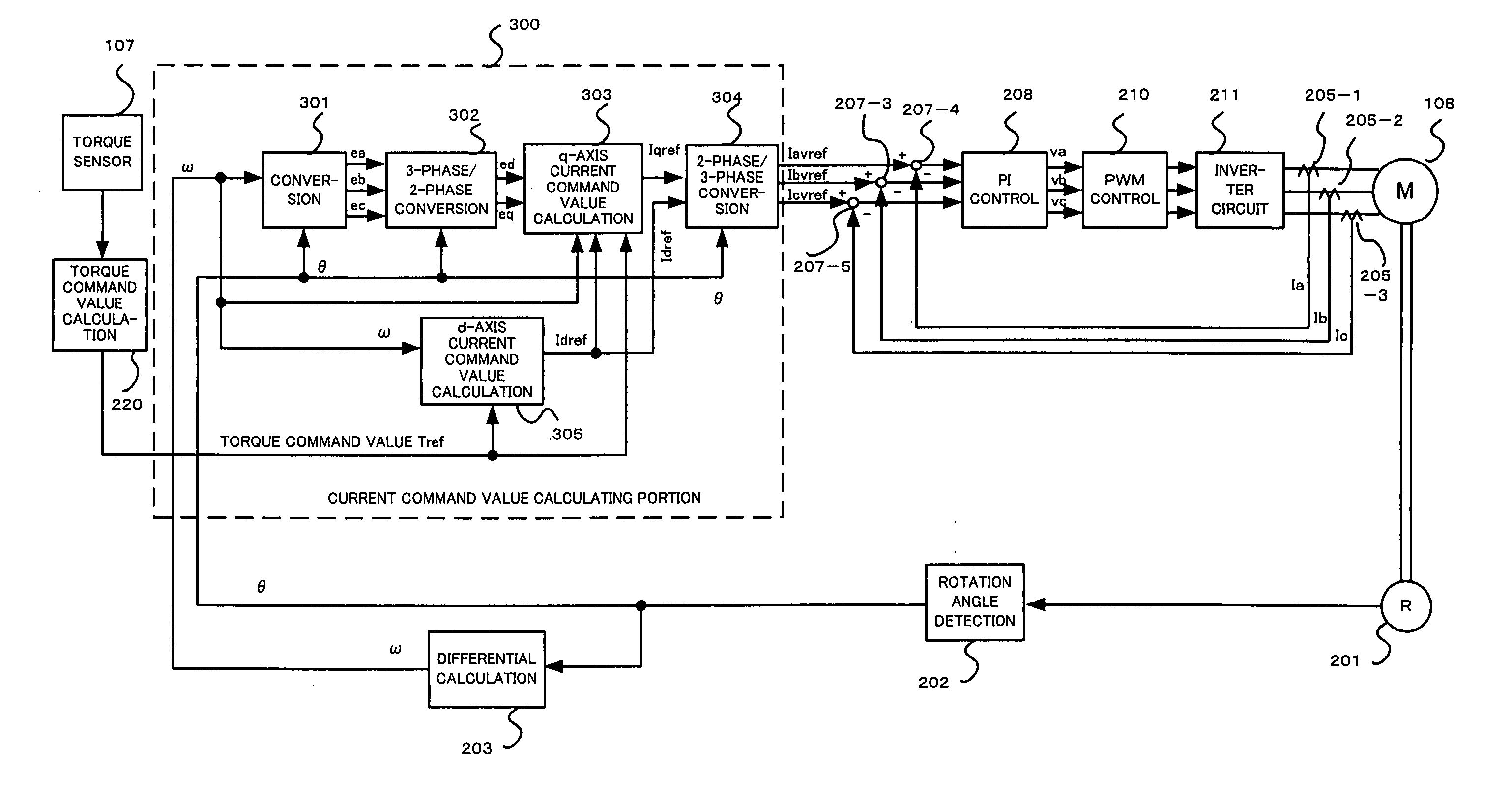
[0035] An embodiment 2 corresponds to an embodiment in the case that the present invention is applied to a control method called as a pseudo vector control (hereinafter, referred to as PVC control) which utilizes a concept of the vector control in the middle of determining the current command value, calculates three phase current command values Iaref, Ibref and Icref as a final current command value, and sets the feedback motor current to three phase Ia, Ib and Ic, as is different from the typical vector control according to the embodiment 1.

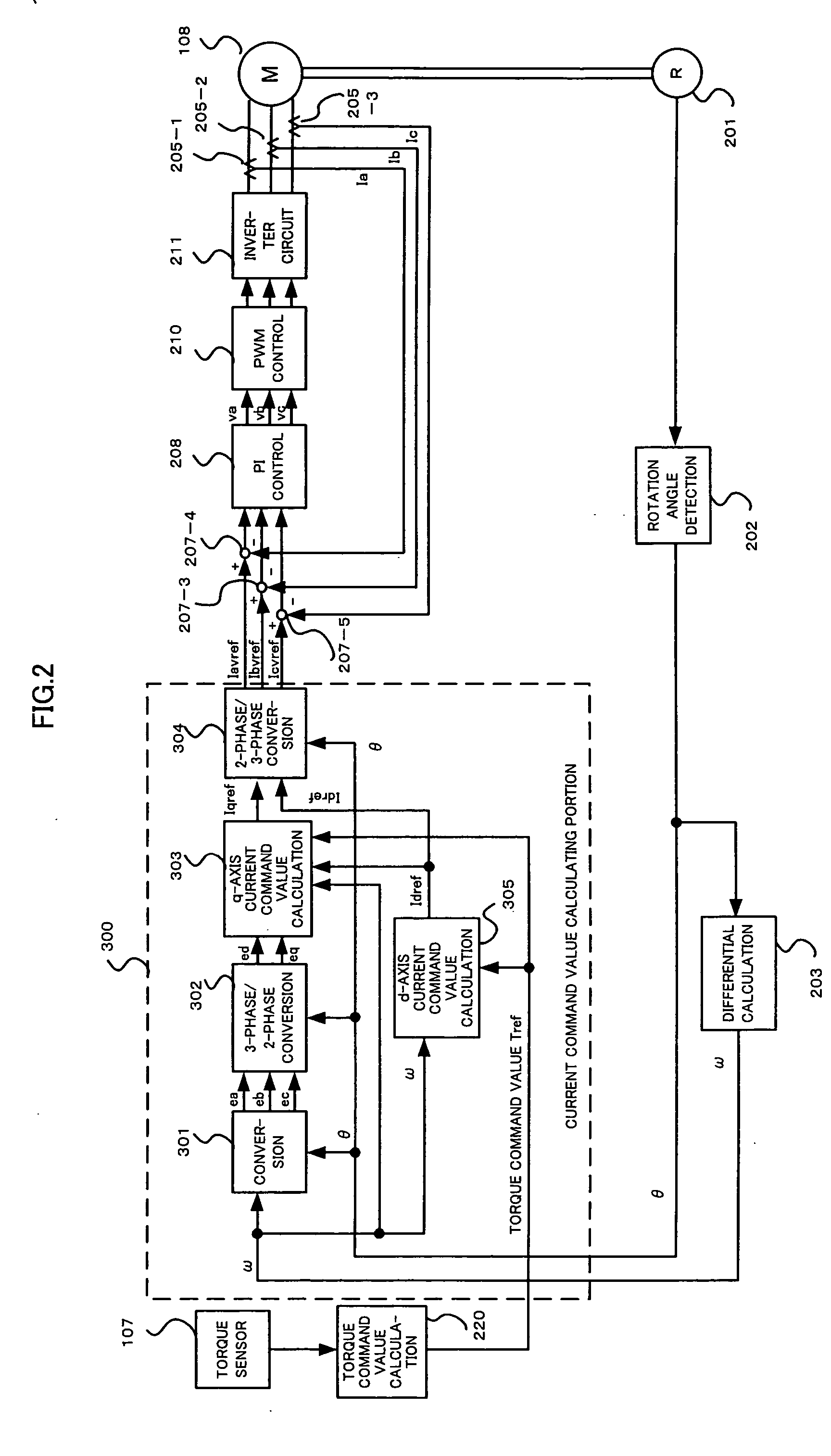
[0036] A description will be given first of the conventional PVC control with reference to FIGS. 2 and 3.

[0037] First, in FIG. 2, if a rotation angle θ output from the position detecting circuit 202 having an output of the angular resolver 201 as an input is input to the differential calculating portion 203, the angular velocity ω is calculated.

[0038] Next, a description will be given of a current command value calculating porti...


PUM


Abstract

In order to solve a problem that a motor generates a noise so as to deteriorate an environment in a vehicle if a field weakening control is executed to the motor of a electric power steering apparatus, in the case that a vehicle speed is high, the same field weakening control as the conventional one is applied to the motor because a noise generated due to a friction between a tire and a road surface and a wind noise of a vehicle body are large, and in the case that the vehicle speed is low, the field weakening control is weakly applied in comparison with the conventional one because the noise generated by the motor is felt relatively largely. Accordingly, the field weakening control can be executed in response to the vehicle speed in such a manner as to make the motor noise smaller.

Description

TECHNICAL FIELD [0001] The present invention relates to a control unit for electric power steering apparatus, and more particularly to a control unit for electric power steering apparatus for reducing a motor noise. BACKGROUND ART [0002] An electric power steering apparatus for applying a steering assist force to a steering mechanism of an automobile by a rotating force of a motor transmits a driving force of the motor by a transmitting mechanism such as a gear or a belt through a reduction gear to apply the steering assist force to a steering shaft or a rack shaft. An example of a brief structure of such an electric power steering apparatus is shown in FIG. 7 and will be described. [0003] A shaft 102 of a steering wheel 101 is coupled to tie rods 106 of steered wheels through a reduction gear 103, universal joints 104a and 104b, and a pinion rack mechanism 105. The shaft 102 is provided with a torque sensor 107 for detecting steering torque of the steering wheel 101, and a motor 10...

Claims


Application Information

Patent Timeline
IPC IPC(8): H02P7/00B62D6/00B62D5/04B62D101/00B62D119/00H02P21/00H02P21/04H02P21/05H02P23/03H02P23/04H02P27/04
CPCB62D5/046
Inventor ENDO, SHUJIAOKI, YUHO
Owner NSK LTD
Why Eureka
Try Eureka