
Backlight device and liquid crystal display apparatus

a backlight device and liquid crystal display technology, applied in the field of backlight devices and liquid crystal display devices, can solve the problems of short useful life, low light emission brightness, and inability to maintain uniform brightness

Active Publication Date: 2007-05-10
SATURN LICENSING LLC
View PDF1 Cites 156 Cited by
  • Summary
  • Abstract
  • Description
  • Claims
  • Application Information

AI Technical Summary

Benefits of technology

[0017] It is an object of the present invention to provide a backlight device and a liquid crystal display apparatus whereby the above problem may be overcome and the utilization efficiency of light radiated from a light source is improved to enable light picture display.
[0018] It is another object of the present invention to provide a backlight device and a liquid crystal display apparatus whereby leakage of light radiated from the light guide spatial section is suppressed to improve the light utilization efficiency as the machining and assembling of respective component parts are facilitated.

Problems solved by technology

This type of the backlight unit has such defects that it is low in light emitting brightness of the cold cathode fluorescent lamp and is of short useful life, and that a low brightness area may be present on the cathode side such that uniform brightness cannot be maintained.
This area lit configuration backlight device also suffers the problem ascribable to the cold cathode fluorescent lamp and, if the device is used for a large format television receiver, exceeding 30 inches, the problem of insufficient brightness or insufficient uniformity of brightness becomes more prominent.
However, if the machining accuracy as well as assembling accuracy of the components is made higher, not only is the production cost raised, but also the production efficiency is deteriorated.
Moreover, it becomes necessary to take measures for shielding the light leaked to the back side, thus leading to a complicated structure.
Even if the surface of the aluminum plate is coated with the insulating material, but if guide through-holes engaged by the LEDs are then formed, the aluminum base material is exposed on the inner peripheral surfaces of the guide through-holes, such that there is a risk that electrical insulation cannot be maintained between the reflective plate and the terminal part of the LED, engaged therewith.
However, if the guide through-hole is increased in size, the gap between it and the LED part, engaged therewith, is also increased to increase further the leakage of the illuminated light to the back side.

Method used


Image

  • Backlight device and liquid crystal display apparatus
  • Backlight device and liquid crystal display apparatus
  • Backlight device and liquid crystal display apparatus

Examples


Embodiment Construction

[0045] Referring to the drawings, an embodiment of the present embodiment, applied to a light transmitting liquid crystal color display apparatus, abbreviated to a liquid crystal display apparatus, will be explained in detail.

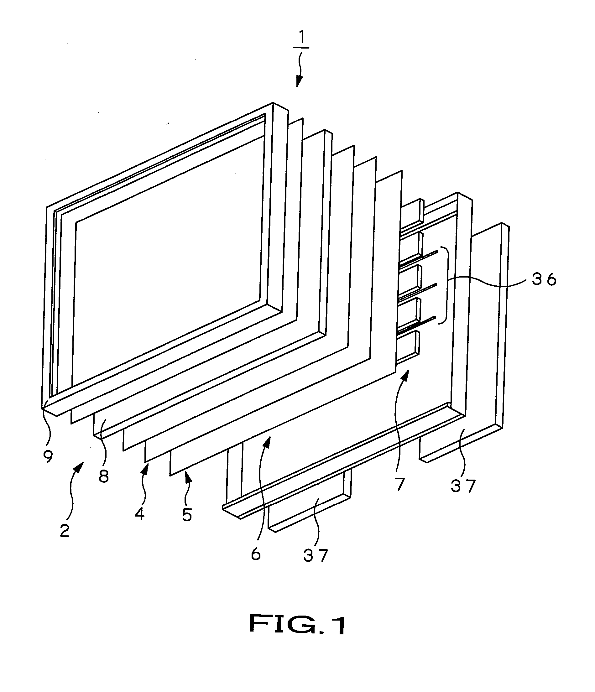
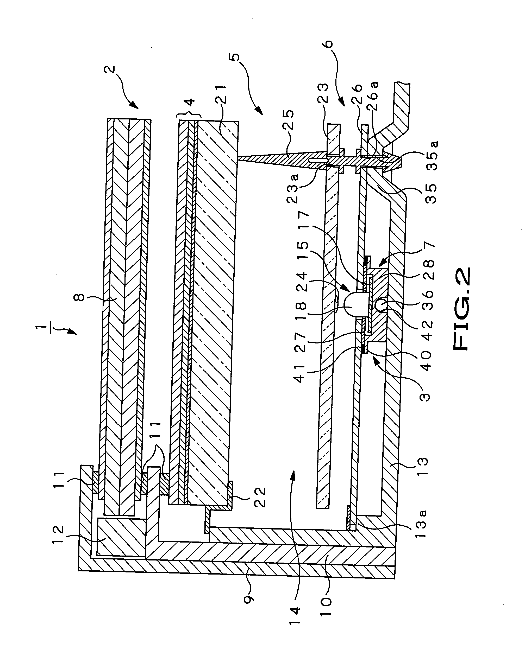
[0046] A liquid crystal display apparatus 1, according to the present invention, is used in, for example, a television receiver or a display monitor apparatus having a large display surface, for example, a 30 inch display surface or larger. Referring to FIGS. 1 and 2, this liquid crystal display apparatus 1 includes a liquid crystal panel unit 2 and a backlight section 3 mounted on the back side of the liquid crystal panel unit 2 to radiate a large volume of illuminating light. Between the liquid crystal panel unit 2 and the backlight section 3, there are arranged an optical converting section 4 for applying predetermined optical conversion to the illuminating light, radiated from the backlight section 3, and for causing the light to fall on the liquid crystal...


PUM


Abstract

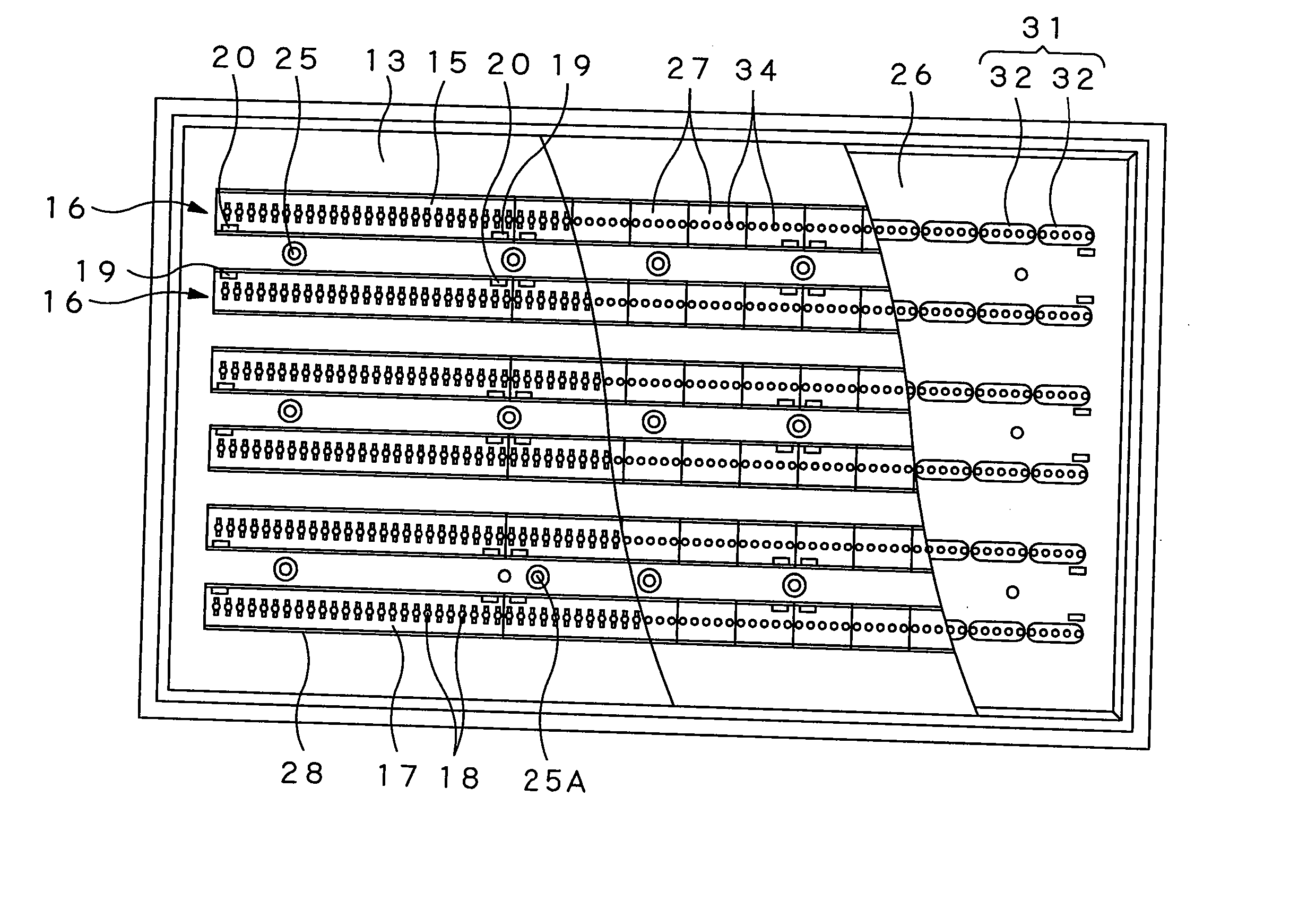
Disclosed is a light transmitting liquid crystal display apparatus used with advantage with a television receiver having a large-sized display not less than 30 inch. A backlight section (3) sending out illuminating light is formed by a plural number of rows made up of many light emitting units (15) arranged on the back surface of a liquid crystal display panel (8). Each light emitting unit includes many LED units (18) mounted on an interconnection substrate (17) and is mounted in this state on a heat dissipating plate (28). A reflecting section (6) for reflecting the light radiated from each LED is formed by a large number of reflective sheet pieces (27), assembled from one heat emitting unit to another, and a reflective plate (26) secured to reflecting plate supports (40) formed on the heat dissipating plate.

Description

TECHNICAL FIELD [0001] This invention relates to a liquid crystal display apparatus, having a light transmitting liquid crystal display (LCD) device, and to a backlight device used for this liquid crystal display apparatus. [0002] The present invention contains subject matter related to Japanese Patent Application JP 2004-228625, filed in the Japanese Patent Office on Aug. 4, 2004, the entire contents of which being incorporated herein by reference. BACKGROUND ART [0003] As compared to the cathode ray tube (CRT), the liquid crystal display apparatus is enlarged in display size, lighter in weight and lower in power usage, so that it is used for a television receiver or for a variety of display devices, as is a self-light-emitting PDP (plasma display panel), as an example. The liquid crystal display device encloses liquid crystal between two transparent substrates of variable sizes and applies electrical voltage across two electrodes provided to the transparent substrates to change th...

Claims


Application Information

Patent Timeline
IPC IPC(8): F21V29/00
CPCG02F1/133603G02F1/133608G02F2001/133628G02F2201/465G02F1/133628
Inventor TABITO, HAFUKATAKEUCHI, HISAKAZUODE, TATSUYA
Owner SATURN LICENSING LLC
Learn More