Plastic fans having improved fan ring weld line strength

Active Publication Date: 2007-05-10
BORG WARNER INC
View PDF4 Cites 27 Cited by
  • Summary
  • Abstract
  • Description
  • Claims
  • Application Information

AI Technical Summary

Benefits of technology

[0010] The present invention relates to a method for increasing the strength of polymeric or fibe

Problems solved by technology

In addition, higher rotational speeds and increased airflow through the fan can lead to de-pitching of the blades and significant noise problems.
Thus, similar to prior cooling fan designs, there is a limit to the amount of force that can be exerted on the ring fans before they fail.
For plastic or fiber reinforced pl

Method used


Image

  • Plastic fans having improved fan ring weld line strength
  • Plastic fans having improved fan ring weld line strength
  • Plastic fans having improved fan ring weld line strength

Examples


Example

[0022] For the purposes of promoting an understanding of the principles of the invention, reference will now be made to the embodiments illustrated in the drawings and specific language will be used to describe the same. It will nevertheless be understood that no limitation of the scope of the invention is thereby intended. The inventions include any alterations and further modifications in the illustrated devices and described methods and further applications of the principles of the invention which would normally occur to one skilled in the art to which the invention relates

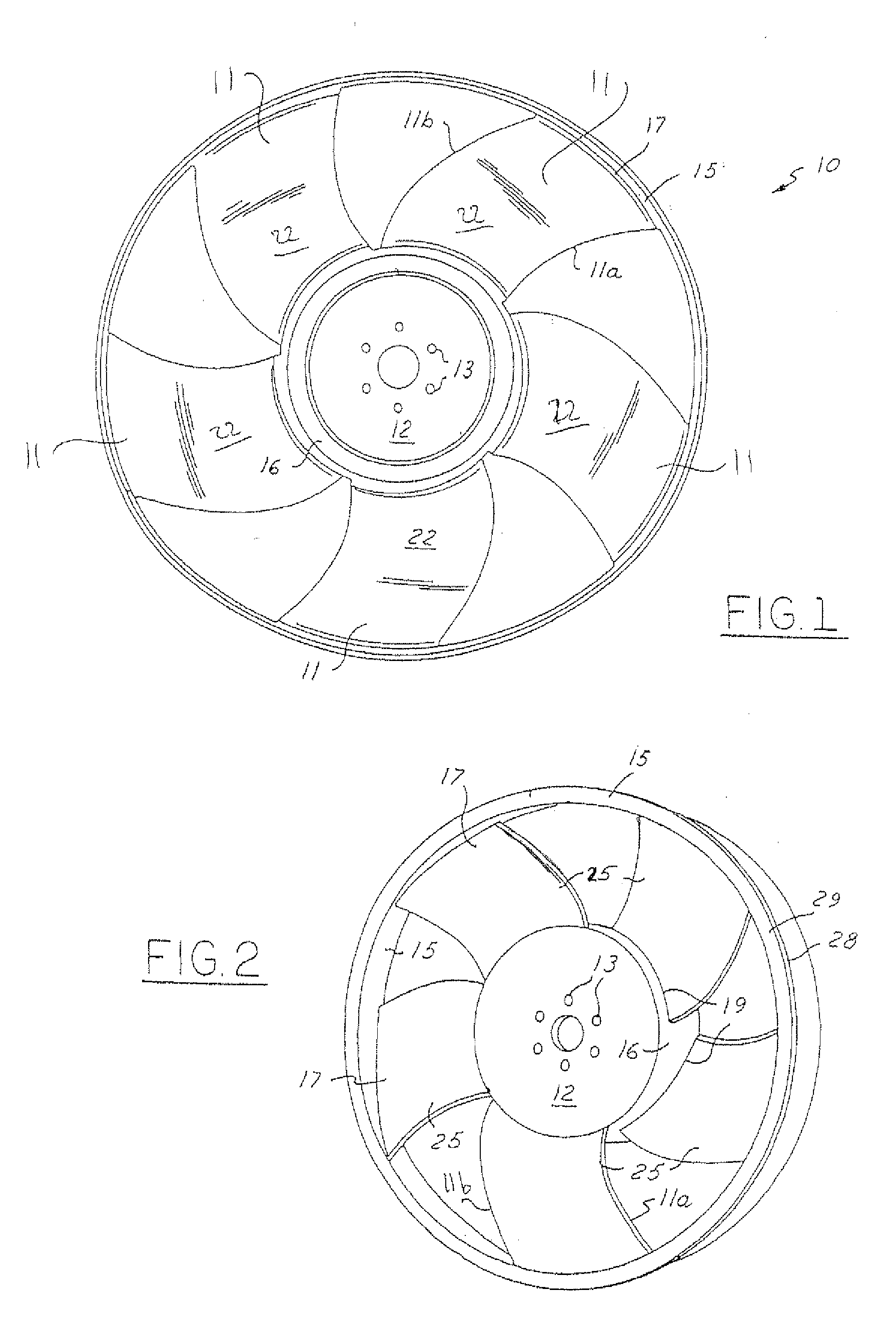
[0023] Referring now to FIGS. 1 and 2, a typical ring fan 10 according to the prior art includes a number of blades 11 mounted to a central hub plate 12. As shown in FIG. 1, the hub plate 12 can include a mounting bolt ring 13 configured to mount the fan to a fan drive assembly of known design. The fan 10 further includes an outer ring 15 fixed to the blade tips 17 of each of the fan blades 11 and an inner rin...


PUM

PropertyMeasurementUnit
Temperatureaaaaaaaaaa
Thicknessaaaaaaaaaa
Pressureaaaaaaaaaa

Abstract

Injection molded ring fan embodiments and methods for making them. The methods influence material flow during the injection molding process such that a major portion of the materials flowing in opposite directions in the outer rings preferably flow past one another, intermix in a swirling relationship, and/or collide at an angle relative to one another. This results in better material mixing or integration of the flow fronts. In one embodiment, the thickness of the outer ring varies in different portions between adjacent fan blades.

Description

CROSS-REFERENCE TO RELATED APPLICATIONS [0001] This is a continuation-in-part of U.S. application Ser. No. 10 / 831,789 filed on Apr. 26, 2004.TECHNICAL FIELD [0002] The invention relates generally to fan drive systems and more specifically to plastic fans having improved fan ring weld line strength. BACKGROUND ART [0003] The present invention concerns cooling fans, such as fans driven by and for use in cooling an industrial or automotive engine. More particularly, certain aspects of the invention relate to a ring fan, while other features concern fan blade design. [0004] In most industrial and automotive engine applications, an engine-driven cooling fan is utilized to draw air through a coolant radiator. Usually, the fan is driven through a belt-drive mechanism connected to the engine crankshaft. [0005] A typical cooling fan includes a plurality of blades mounted to a central hub plate. The hub plate can be configured to provide a rotary connection to the belt drive mechanism, for ex...

Claims


Application Information

Patent Timeline
IPC IPC(8): B63H1/16B29C33/38B29C45/00B29C45/26B29C45/37B29C45/76B29L31/08F04D3/00F04D29/32F24F13/08
CPCB29C33/3835B29C45/0025Y10S415/915F04D29/326B29L2031/08F04D29/023F05D2300/43F01P5/02B29C45/76B29B11/08
Inventor STAGG, JONATHAN B.BUCKLEY, DONALD E.
Owner BORG WARNER INC
Why Eureka
Try Eureka