Control device of vehicle

a control device and vehicle technology, applied in the direction of fluid gearings, machine/engine, process and machine control, etc., can solve the problems of reducing the degree of connection of the clutch, reducing the target slippage, and improving the response of the deceleration

Inactive Publication Date: 2007-05-10
TOYOTA JIDOSHA KK
View PDF6 Cites 11 Cited by
  • Summary
  • Abstract
  • Description
  • Claims
  • Application Information

AI Technical Summary

Benefits of technology

[0020] According to this invention, when the detector detects the preference allowing the rapid deceleration, the torque converter that is an example of the fluid coupling is set to reduce the target slippage and thereby to improve the responses of the deceleration and reacceleration so that the deceleration feeling matching with the driver's preference can be achieved. The manner of achieving the target slippage in the fluid coupling is not restricted and, for example, such a manner may be employed that con

Problems solved by technology

Thereby, the driver may feel unnecessary acceleration, and/or may operate a brake more times so that acceleration feeling requested by the driver cannot be achieved in some cases.
Although a vehicle drive force control device disclosed in Japanese Patent Laying-Open No. 10-095252 can achieve the target d

Method used


Image

  • Control device of vehicle
  • Control device of vehicle
  • Control device of vehicle

Examples


Embodiment Construction

[0033] Embodiments of the invention will now be described with reference to the drawings. In the following description and drawings, the same parts bear the same reference numbers and the same names, and achieve the same functions. Therefore, description thereof is not repeated.

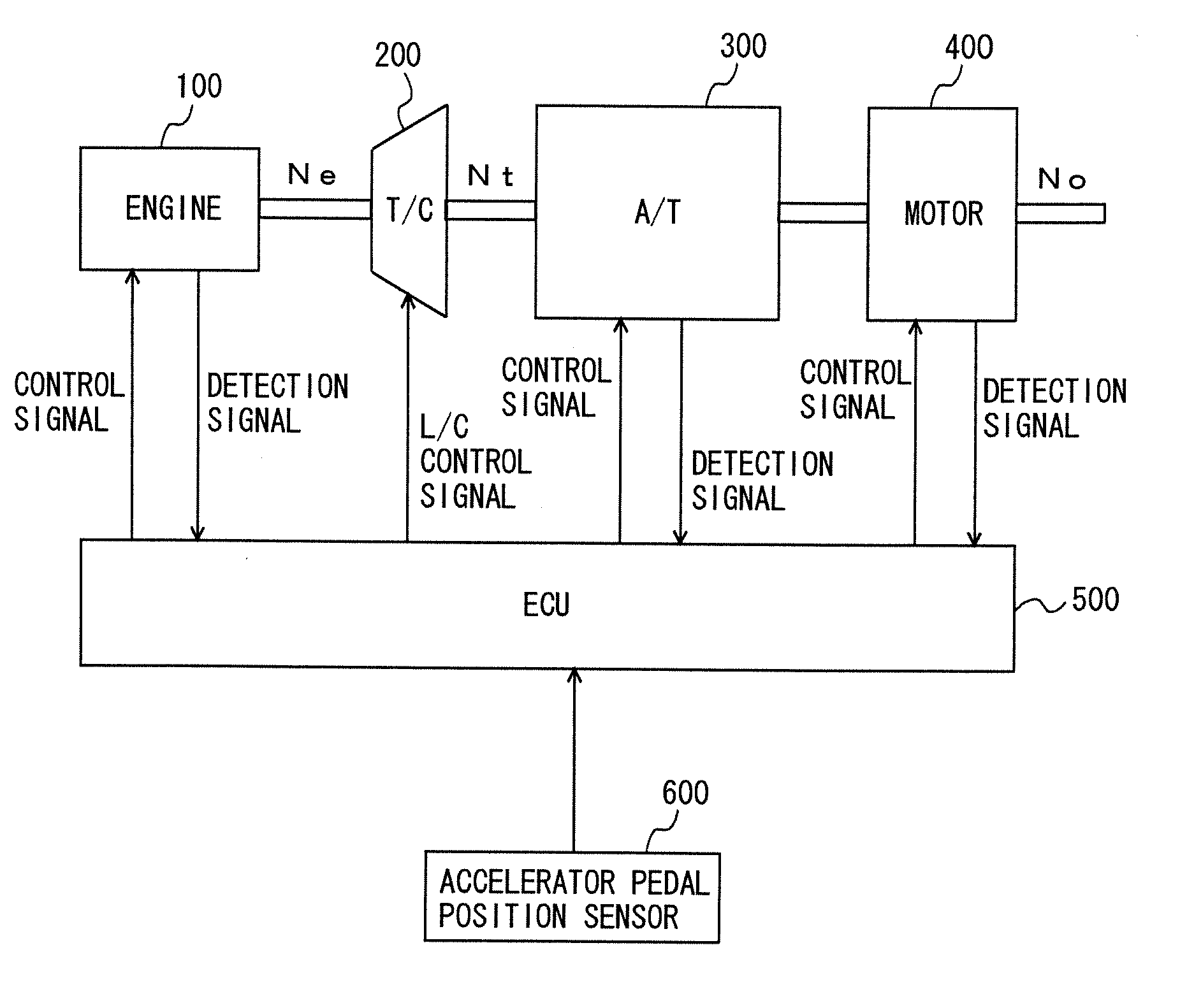
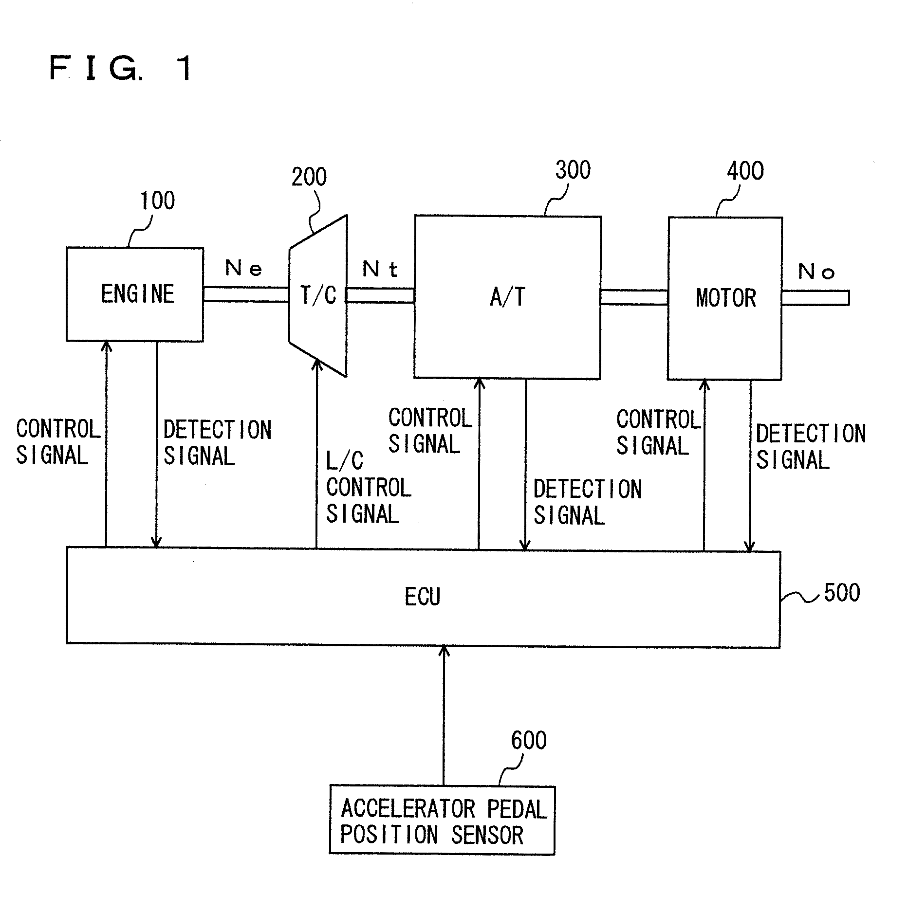
[0034]FIG. 1 illustrates a power train of a vehicle including an ECU that is a control device according to an embodiment of the invention.

[0035] As shown in FIG. 1, this vehicle includes an engine 100, a torque converter 200, an automatic transmission 300, an electric motor 400 assisting the engine, an ECU (Electronic Control Unit) 500 controlling them and an accelerator pedal position sensor 600 providing a signal indicative of a position of an accelerator pedal to ECU 500.

[0036] The following description will be given on a drive power control that is applied to the power train having engine 100, torque converter 200, automatic transmission 300 and motor 400 as shown in FIG. 1. However, the invention is n...


PUM


Abstract

An ECU executes a program including a step of detecting a driver's preference potential Hdr, a step of calculating a target engine output Ptgt using Hdr when a deceleration request is detected, a step of calculating a target slippage tsl using Hdr, a step of calculating a target engine speed tne, a step of calculating a target ISC opening tidle from Ptgt and tne, a step of assigning a guard value to tidle when tidle is smaller than the guard value, a step of calculating a current engine output Pnow and a step of calculating a motor output (regeneration quantity) Phv from (Ptgt−Pnow).

Description

[0001] This nonprovisional application is based on Japanese Patent Application No. 2005-323572 filed with the Japan Patent Office on Nov. 8, 2005, the entire contents of which are hereby incorporated by reference. BACKGROUND OF THE INVENTION [0002] 1. Field of the Invention [0003] The present invention relates to a control device of a vehicle provided with a power train having an engine and an automatic transmission, and particularly to a control device of a vehicle that can achieve deceleration matching with a driver's preference. [0004] 2. Description of the Background Art [0005] In generally, an automatic transmission connected to an engine of a vehicle is automatically controlled by determining a transmission gear ratio depending on an operation amount of an accelerator pedal by a driver and a vehicle speed. During ordinary driving, the gear ratio is increased with decrease in accelerator pedal operation amount or with increase in vehicle speed. [0006] Therefore, during downhill...

Claims


Application Information

Patent Timeline
IPC IPC(8): G06F17/00B60K6/48B60K6/547B60L50/16B60W10/02B60W10/06B60W10/08B60W10/18B60W20/00F02D29/00F02D29/02F02D41/12F16H59/42F16H61/14
CPCB60K6/48Y10S477/902B60W10/02B60W10/023B60W10/06B60W10/08B60W20/00B60W30/18109B60W2540/30B60W2710/065B60W2720/106Y02T10/6221Y02T10/6286Y10T477/65Y10S477/901B60K6/547Y02T10/62B60W10/10B60W30/18136B60W2710/0644
Inventor OGAWA, HIROYUKI
Owner TOYOTA JIDOSHA KK
Why Eureka
Try Eureka