Verification of Continuity

a continuity and verification technology, applied in the direction of flow monitors, blast furnace components, and solids analysis using ultrasonic/ultrasonic/infrasonic waves, can solve the problems of ambiguity regarding, error in making incorrect connections, and the likelihood of incorrect connections, etc., to achieve cost-effective and simple effects

Inactive Publication Date: 2007-05-17
ARNOLD DAVID HOWARD +1
View PDF5 Cites 36 Cited by
  • Summary
  • Abstract
  • Description
  • Claims
  • Application Information

AI Technical Summary

Benefits of technology

[0005] The primary objective of this invention is to provide a cost-effective and simple methodology to ensure that the correct fluid source is used, either via a gravity fed system or via a pumped arrangement. The invention is based on using pulses of either ultrasound, light or pressure being transmitted along the tube from one end to the other. The pressure pulse can be in the form of a burst of sound or a single impulse. A transmitter provides the source of ultrasound, light or pressure and the receiver detects the ultrasound, light or pressure as ...

Problems solved by technology

This leads to ambiguity regarding which is the correct tube to use and the likelihood that incorrect connections will be made.
Typically there are a number of line sets used, may be 10 or more, and within the confined and crowded environment of the operating t...

Method used


Image

  • Verification of Continuity
  • Verification of Continuity
  • Verification of Continuity

Examples


Embodiment Construction

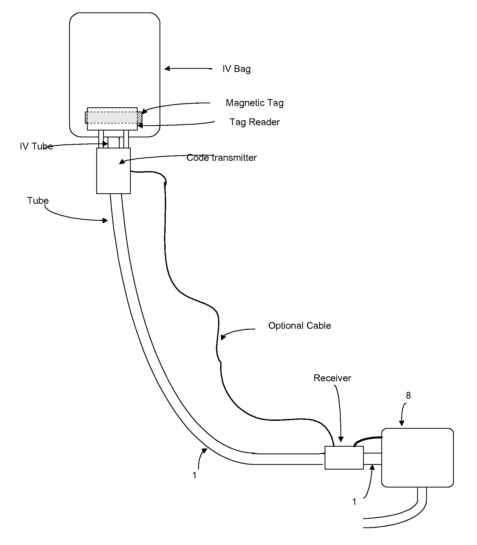
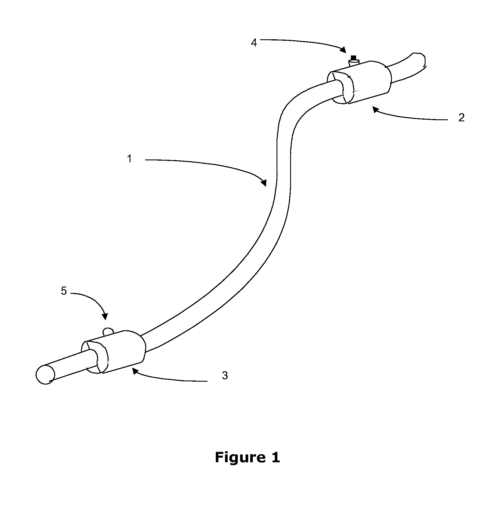
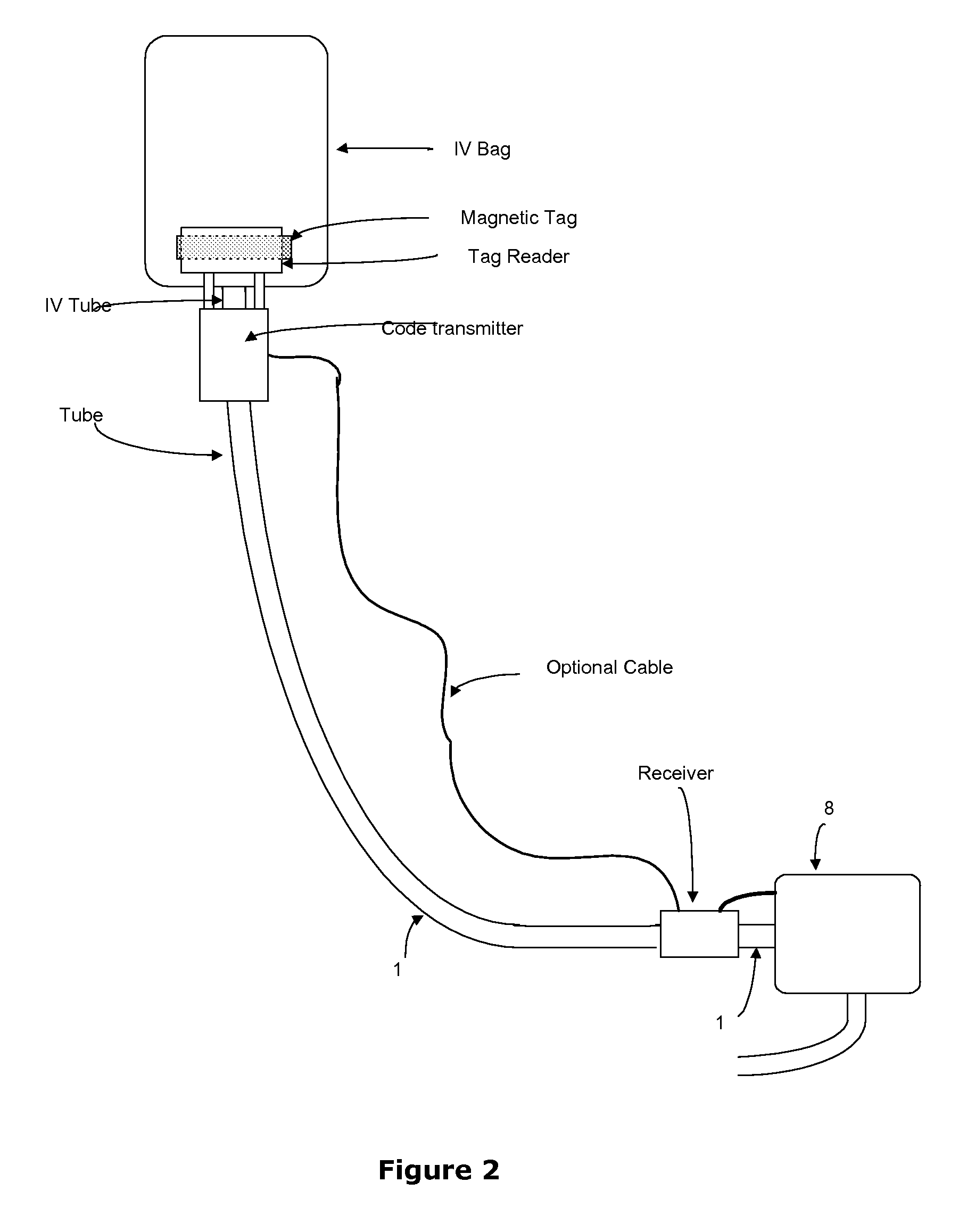
[0012] As shown in FIG. 1 a flexible plastic tube 1 is used to transfer fluids from one end to the other, the method of transfer being either gravity fed or pumped. In its simplest embodiment a source of pulsed pressure or light will be applied to one end of the tube using a transmitter 2 clamped around the tube. At the other end a receiver 3 would be clamped around the tube to detect the pulsed pressure or light as appropriate. The transmitter or receiver do not require any preferred orientation relative to the tube.

[0013] In the most basic embodiment the transmitter is operated manually with a switch 4 mounted on the transmitter. An indicator 5 on the receiver will only activate if it receives the pulse from the transmitter on the same tube. The indicator may be a light emitting diode or a beeper. The transmitter and receiver can be hinged cylinders that clamp around the tube, and can be removed and re-positioned without removing the tube.

[0014] The transmitter may consist of ei...


PUM


Abstract

Techniques are described for eliminating the potential continuity errors in fluid connection devices, such as tubes, which can arise in complex systems where many tubes are used. The techniques are based upon the use of ultrasound, light or pressure waves being transmitted along the connecting device using a transmitter and a receiver at either end. Methods are described to cover the external coupling of the transmitter and/or the receiver into the tubing thereby eliminating the need to compromise the connection. The described apparatus can be external to the system or integrated within it. The potential to carry information along the connection device is also disclosed.

Description

CROSS REFERENCE TO RELATED APPLICATIONS [0001] This application claims priority to and the benefit of the following application GB 0522899.4 filed Nov. 10, 2005. BACKGROUND OF THE INVENTION [0002] The use of plastic or glass tubing as a connecting device for fluids is well known and is used extensively in a wide range of applications such as in the food / beverage and medical fields. The tubing provides a contained method by which fluids are transferred from one point to another; the transfer may be gravity fed or pumped. [0003] In some applications there may be many tubes in close proximity which are indistinguishable from each other as they have similar or identical form. This leads to ambiguity regarding which is the correct tube to use and the likelihood that incorrect connections will be made. [0004] An example of this situation is in hospital operating theatres where tubes (“line sets”) are used to connect fluids in i / v bags to delivery units; the fluid transfer may be pumped or...

Claims


Application Information

Patent Timeline
IPC IPC(8): G01N29/04A61M5/14A61M5/172
CPCA61M5/14A61M5/172A61M2205/3569A61M2205/3576A61M2205/6018A61M5/1407A61M5/16827
Inventor ARNOLD, DAVID HOWARDDICKINSON, ROBERT JULIAN
Owner ARNOLD DAVID HOWARD
Why Eureka
Try Eureka