
Closed crankcase ventilation system

a technology of ventilation system and crankcase, which is applied in the direction of mechanical equipment, machines/engines, and non-fuel substance addition to fuel, etc., can solve the problems of affecting the sealing or fitting of the piston and the cylinder, placing undesirable parts of the crankcase emissions directly into the environment, and fouling the compressor wheel in a relatively short time period, so as to enhance the venting of crankcase emissions and enhance the flow of crankcase emissions

Inactive Publication Date: 2007-05-17
CATERPILLAR INC +1
View PDF60 Cites 21 Cited by
  • Summary
  • Abstract
  • Description
  • Claims
  • Application Information

AI Technical Summary

Benefits of technology

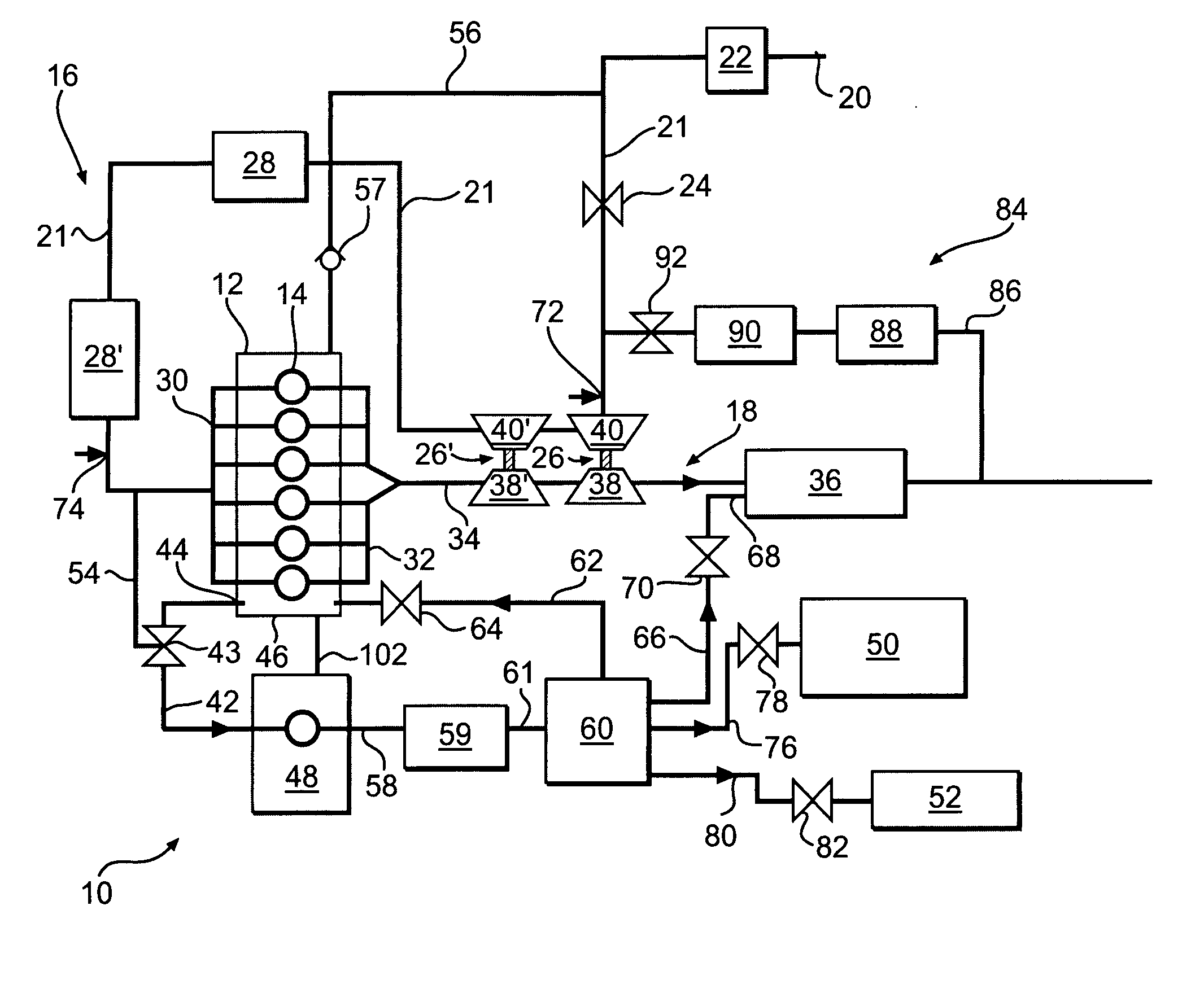
[0012] In one aspect, the present disclosure is directed to a closed crankcase ventilation system for an internal combustion engine. A compressor is configured to compress air and enhance the venting of crankcase emissions from a crankcase of the engine. A flow path extends between the crankcase and an intake of the compressor. A prioritizing device is configured to regulate the flow of crankcase emissions and control pressure within the crankcase. A treatment element is located downstream of the compressor for treating the air and crankcase emissions to remove entrained oil. A first conduit is located downstream of the treatment element and is configured to introduce a first portion of the air and crankcase emissions into one of an exhaust system for the engine and an air intake system for the engine. A second conduit is located downstream of the treatment element and is configured to introduce a second portion of the air and crankcase emissions into a system having at least one component utilizing compressed air for its operation.
[0013] In another aspect, the present disclosure is directed to a method for closed crankcase ventilation comprising providing a flow path to vent crankcase emissions from the crankcase of an internal combustion engine. The flow of crankcase emissions is regulated and the pressure within the crankcase is controlled by a prioritizing device. A compressor is used to enhance the flow of crankcase emissions through the flow path. Air and crankcase emissions from the crankcase are compressed. The air and crankcase emissions are treated to remove entrained oil. A first portion of the treated air and crankcase emissions is introduced into one of an exhaust system for the engine and an air intake system for the engine. A second portion of the treated air and crankcase emissions is utilized to operate at least one component utilizing compressed air for its operation.

Problems solved by technology

The seal or fit between pistons and cylinders is not perfect.
Such venting may place undesirable portions of crankcase emissions directly into the environment.
Returning crankcase emissions to the intake side of a compressor in a supercharger or turbocharger can result in fouling of the compressor wheel in a relatively short time period.
Additionally, cooling units downstream of a supercharger or turbocharger may be fouled.
Further, even with extensive purification, some level of contamination may still exist that may be harmful to the supercharger or turbocharger, cooling units, or various engine components.
In addition, it may sometimes be necessary to provide some type of pumping unit to assist in venting blow-by gases and resulting crankcase emissions from the crankcase of the engine of the machine.
Blow-by gases and resulting crankcase emissions may likewise vary over the life of an engine as relevant parts encounter wear and tear from use.
Variations in blow-by gases and crankcase emissions may cause significant fluid flow variations in venting the crankcase emissions.
The efficiency of dual use of the compressor is lacking since the compressed fluid exiting the compressor is not available for components which use compressed air for their operation.
Products of combustion present in the crankcase emissions are left untreated and allowed to directly enter the engine intake where they may cause engine damage.

Method used


Image

  • Closed crankcase ventilation system
  • Closed crankcase ventilation system
  • Closed crankcase ventilation system

Examples


Embodiment Construction

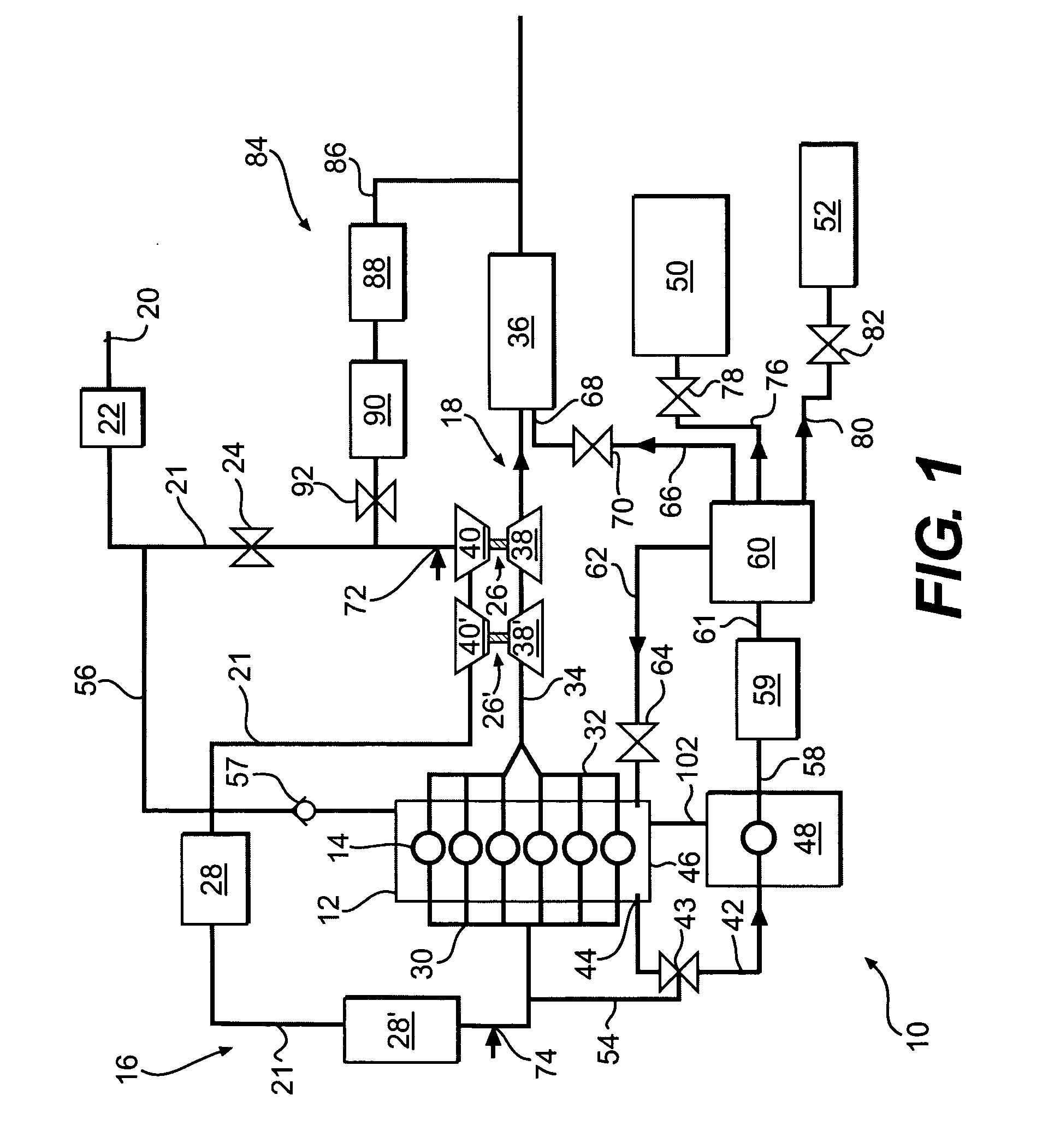
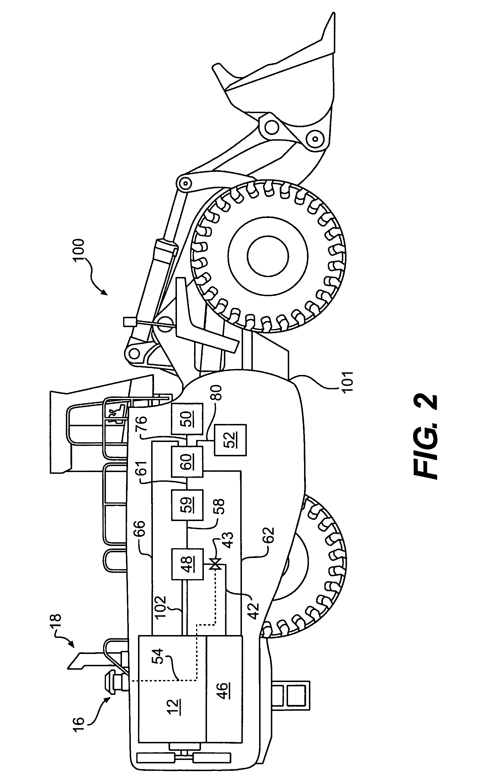
[0016]FIG. 1 illustrates an exemplary closed crankcase ventilation (CCV) system 10. CCV system 10 may include an internal combustion engine 12. Engine 12 may include combustion cylinders 14 for generating power. Engine 12 may be provided with an air intake system 16 and an exhaust system 18. Air intake system 16 may include various components including, for example, intake opening 20, air filter 22, throttle valve 24, one or more turbochargers 26, 26′, one or more cooling modules 28, 28′, and intake manifold 30. The various components of air intake system 16 may be located along an intake flow path, such as, for example, intake conduit 21. Exhaust system 18 may include various components including, for example, exhaust manifold 32, exhaust conduit 34, and aftertreatment module 36.

[0017] The one or more turbochargers 26, 26′ may be composed of components forming a part of both the air intake system 16 and the exhaust system 18. Turbocharger 26 is composed of a turbine section 38 loc...


PUM


Abstract

A closed crankcase ventilation system for an internal combustion engine is disclosed. A compressor is configured to compress air and enhance the venting of crankcase emissions from a crankcase of the engine. A flow path is provided between the crankcase and an intake of the compressor. A prioritizing device is situated in the flow path and configured to regulate the flow of crankcase emissions and control pressure within the crankcase. A treatment element is provided downstream of the compressor and configured to treat the compressed air and crankcase emissions to remove entrained oil. A first conduit downstream of the treatment element is configured to introduce a first portion of the compressed air and crankcase emissions into one of an exhaust system for the engine and an air intake system for the engine. A second conduit downstream of the treatment element is configured to introduce a second portion of the air and crankcase emissions into a system having at least one component utilizing compressed air for its operation.

Description

[0001] This application claims the benefit of U.S. Provisional Application No. 60 / 731,484, filed Oct. 31, 2005.TECHNICAL FIELD [0002] This disclosure relates to a closed crankcase ventilation system and, more particularly, to a closed crankcase ventilation system for internal combustion engines. BACKGROUND [0003] In internal combustion engines, fuel and air may be introduced into cylinders for combustion. Pistons may move within the cylinders under the influence of a crankshaft located in a crankcase. In each cylinder, a piston may compress the fuel and air mixture preparatory to combustion of the mixture. Combustion may then drive the pistons and yield power output. The power output may be used to drive a machine. Along with the desired output of power, combustion products are created. Most of these combustion products are exhausted from the cylinder into an exhaust system. [0004] The seal or fit between pistons and cylinders is not perfect. Some of the combustion products may blow...

Claims


Application Information

Patent Timeline
Patent Type & Authority Applications(United States)
IPC IPC(8): F02B25/06
CPCF01M13/021F01M2013/0005F01M2013/026F01N3/326F01N13/107F02B29/0412F02B37/013F02B37/10F02M25/06Y02T10/121Y02T10/146Y02T10/20Y02T10/12
Inventor MONCELLE, MICHAEL E.MONCELLE, PATRICIAYOUNG, D. CRAIGCAZZATO, ANTHONYFORNOF, WILLIAM P.REISINGER, PAUL G.
Owner CATERPILLAR INC
Learn More