In-wheel motor system

a technology of in-wheel motors and motor components, which is applied in the direction of electric propulsion mounting, couplings, transportation and packaging, etc., can solve the problems of high total system cost, and achieve the effects of low stiffness of the connection members themselves, easy assembly, and improved work efficiency

Inactive Publication Date: 2007-05-17
BRIDGESTONE CORP
View PDF8 Cites 26 Cited by
  • Summary
  • Abstract
  • Description
  • Claims
  • Application Information

AI Technical Summary

Benefits of technology

[0023] According to the present invention, the motor rotor and the wheel or hub are interconnected by a coupling mechanism which comprises a motor-side plate, wheel-side plate, intermediate plate, and first and second connection members for interconnecting the motor-side plate and the intermediate plate and interconnecting the intermediate plate and the wheel-side plate in such a manner that the connected plates can move relative to each other in a direction where the stiffness of the connection members themselves is low, for example, rubber members whose length is large in the connection direction, therefore, whose stiffness is high in the connection direction and low in the direction orthogonal to the connection direction, the first and second connection members being arranged such that the directions where their stiffness is low become orthogonal to each other and which is simple in structure and has a small number of parts. Therefore, the coupling mechanism is easily assembled, thereby making it possible to improve work efficiency.
[0024] At this point, when at least one pair of either one or both of the above first and second connection members are provided and the paired connection members are arranged at positions where they become symmetrical to the center line of the plane of the plates, unrequired twist can be prevented, thereby making it possible to transmit the torque of the motor without fail.
[0025] When the above first and second connection members are attached to the respective plates through a bearing or a rubber bush, the movement of the coupling mechanism becomes smooth, thereby making it possible to further improve power transmission efficiency.
[0026] When the above first and second connection members are attached to the respective plate while they are compressed in the connection direction, the stroke between the plates can be made long, thereby making it possible to handle input of large vibration.

Problems solved by technology

Further, since the above direct-acting guides 62A and 62B are expensive, the whole system costs dear.

Method used


Image

  • In-wheel motor system
  • In-wheel motor system
  • In-wheel motor system

Examples


Embodiment Construction

[0037] Preferred embodiments of the present invention will be described hereinunder with reference to the accompanying drawings.

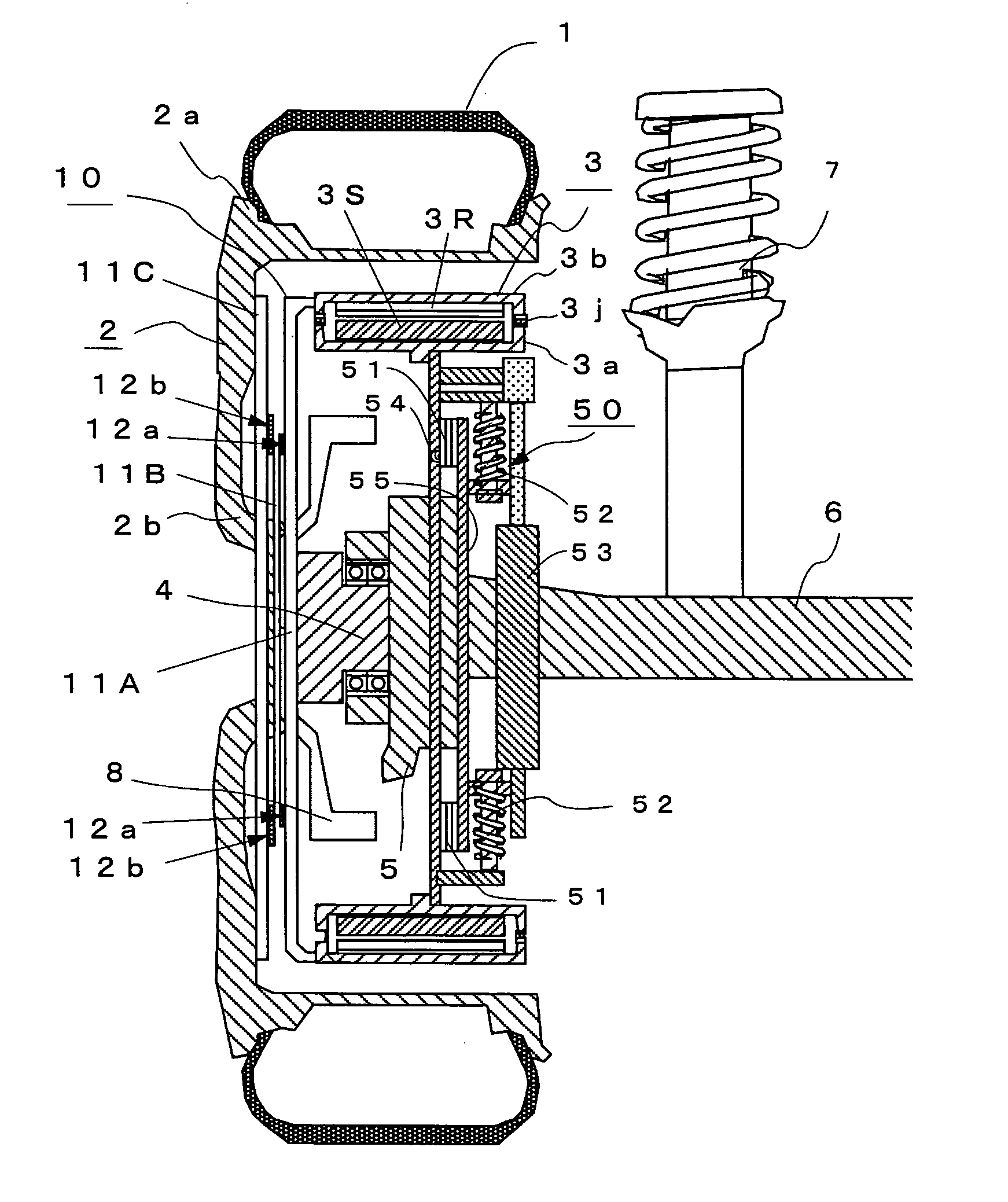
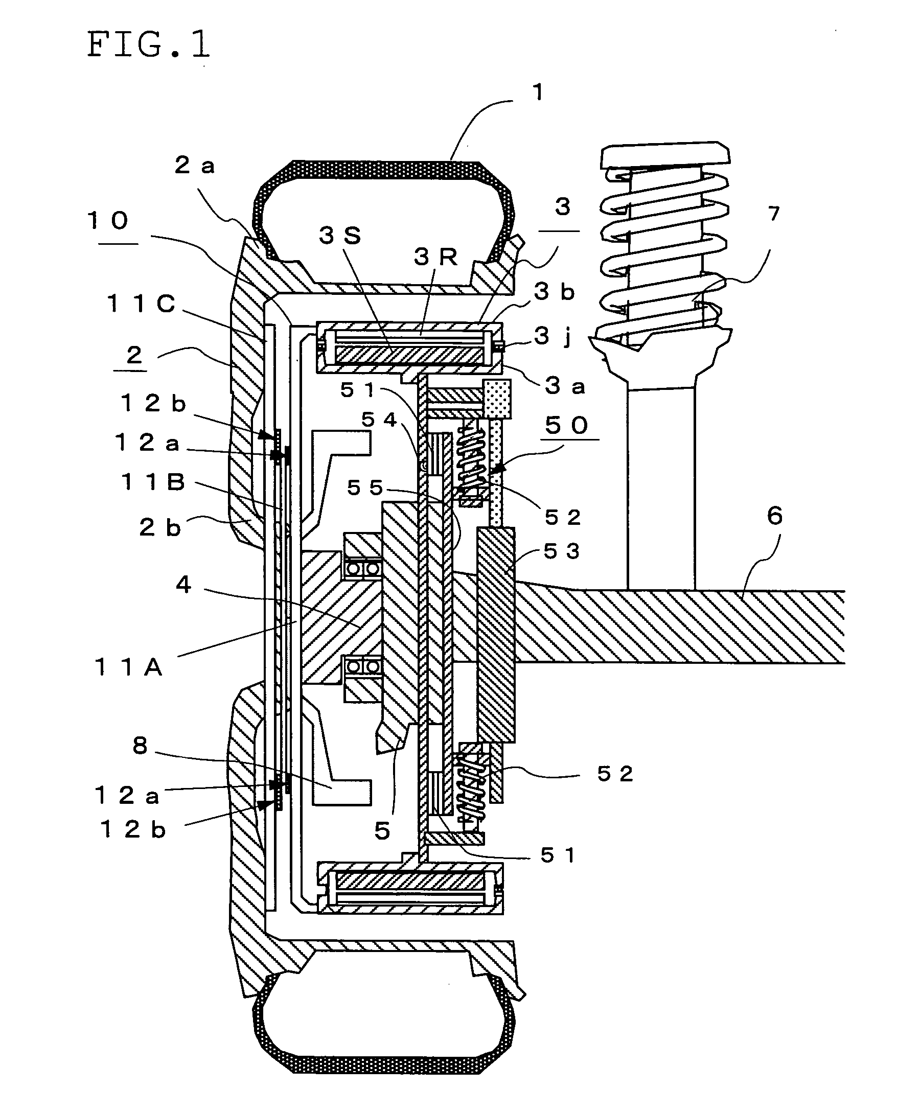
[0038]FIG. 1 shows the constitution of an in-wheel motor system according to a preferred embodiment of the present invention. In FIG. 1, reference numeral 1 denotes a tire, 2 a wheel consisting of a rim 2a and a wheel disk 2b, and 3 an outer rotor type in-wheel motor which comprises a stator 3S fixed to a non-rotating side case 3a arranged on the inner side in the radial direction and a rotor 3R fixed to a rotating side case 3b rotatably connected to the above non-rotating side case 3a through a bearing 3j and arranged on the outer side in the radial direction.

[0039] Numeral 4 denotes a hub connected to the wheel 2 at its rotary shaft, 5 a knuckle connected to an axle 6, 7 a suspension member composed of a shock absorber, 8 a brake unit composed of a brake disk mounted to the above hub 4, 10 a rubber flexible coupling of the present invention for connecti...


PUM


Abstract

An in-wheel motor system having a flexible coupling for transmitting the drive torque of a motor to a wheel. The flexible coupling 10 simple in structure and easily assembled comprises a motor-side plate (11A) mounted to the rotating side case of the motor, a wheel-side plate (11C) mounted to the wheel or a hub, an intermediate plate (11B) disposed between these two plates (11A) and (11C), a first rubber member (12a) of generally rectangular shape in plan view which connects the motor-side plate (11A) to the intermediate plate (11B) in such a manner that they can move relative to each other in a direction (direction B) orthogonal to their connection direction (direction A), and a second rubber member (12b) formed in the same manner as the first rubber member (12a) which connects the intermediate plate (11B) to the wheel side plate (11C) in such a manner that they can move relative to each other in the direction A orthogonal to the direction B.

Description

BACKGROUND OF THE INVENTION [0001] 1. Field of the Invention [0002] The present invention relates to an in-wheel motor system for use in a vehicle having direct drive wheels as drive wheels. [0003] 2. Description of the Prior Art [0004] It is generally known that, in a vehicle having a suspension mechanism such as a spring around a wheel, as the mass of parts under the spring such as a wheel, knuckle and suspension arm, so-called “unsprung mass” increases, changes in the ground holding force of a tire when running on an uneven road become larger, thereby deteriorating road holding properties. [0005] In a vehicle driven by a motor such as an electric car, an in-wheel motor system incorporating a motor in a wheel is being employed. However, in a conventional in-wheel motor whose non-rotating part is fixed to a spindle shaft connected to a part such as an upright or knuckle which is one of the parts around a wheel of the vehicle and whose rotor as a rotating part can rotate together wi...

Claims


Application Information

Patent Timeline
Patent Type & Authority Applications(United States)
IPC IPC(8): B60K7/00B60K17/02F16D3/62F16D3/78F16F1/373H02K7/00
CPCB60K7/0007B60K17/02F16D3/62F16D3/78F16F1/373
Inventor SUZUKI, YASUHIROTASHIRO, KATSUMI
Owner BRIDGESTONE CORP
Why Eureka
Try Eureka