Fuel cell voltage measurement device

Active Publication Date: 2007-05-17
IND TECH RES INST
View PDF4 Cites 17 Cited by
  • Summary
  • Abstract
  • Description
  • Claims
  • Application Information

AI Technical Summary

Benefits of technology

[0005] A primary object of the present invention is to provide a fuel cell voltage measurement device adapted

Problems solved by technology

However, from the viewpoints of thermodynamics and kinetics, due to the temperature distribution in different zones and the flowing of reactant gas, it is unable to ensure that all the monocells could operate under identical conditions.
Moreover, errors produced in the process of assembling the fuel cell bank would possibly cause gas leakage in some of the monocells or the phenomenon

Method used


Image

  • Fuel cell voltage measurement device
  • Fuel cell voltage measurement device
  • Fuel cell voltage measurement device

Examples


Embodiment Construction

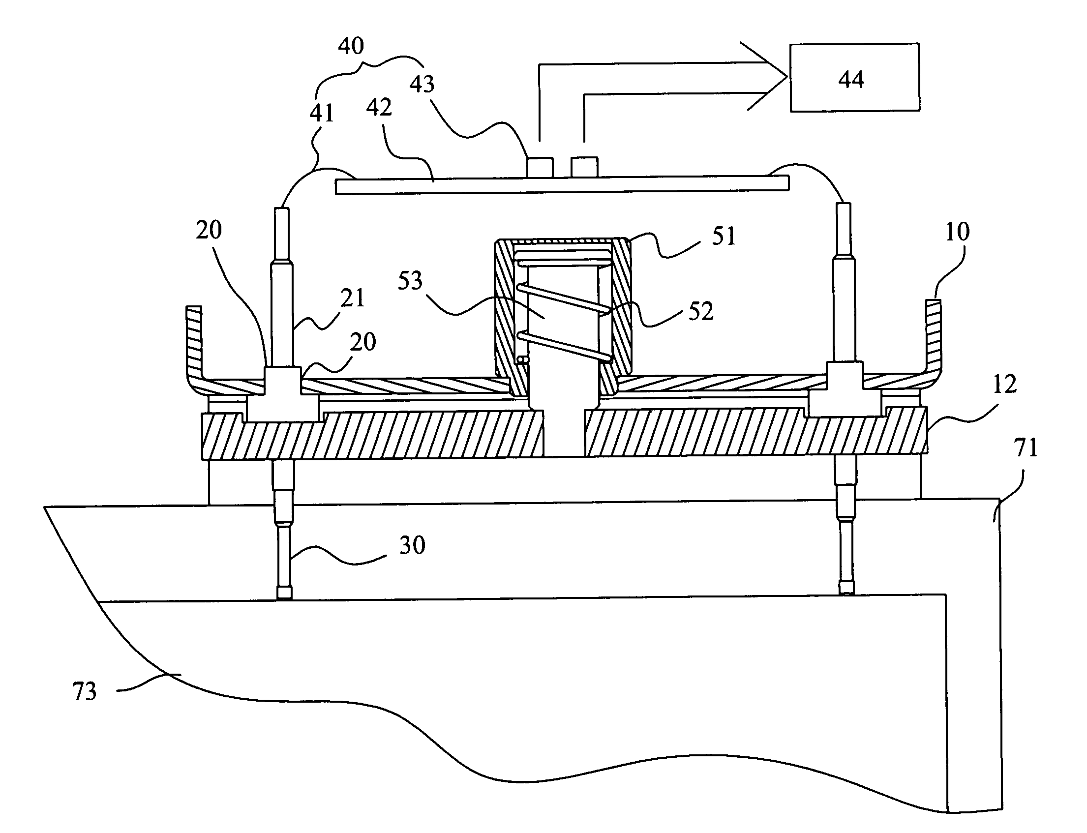
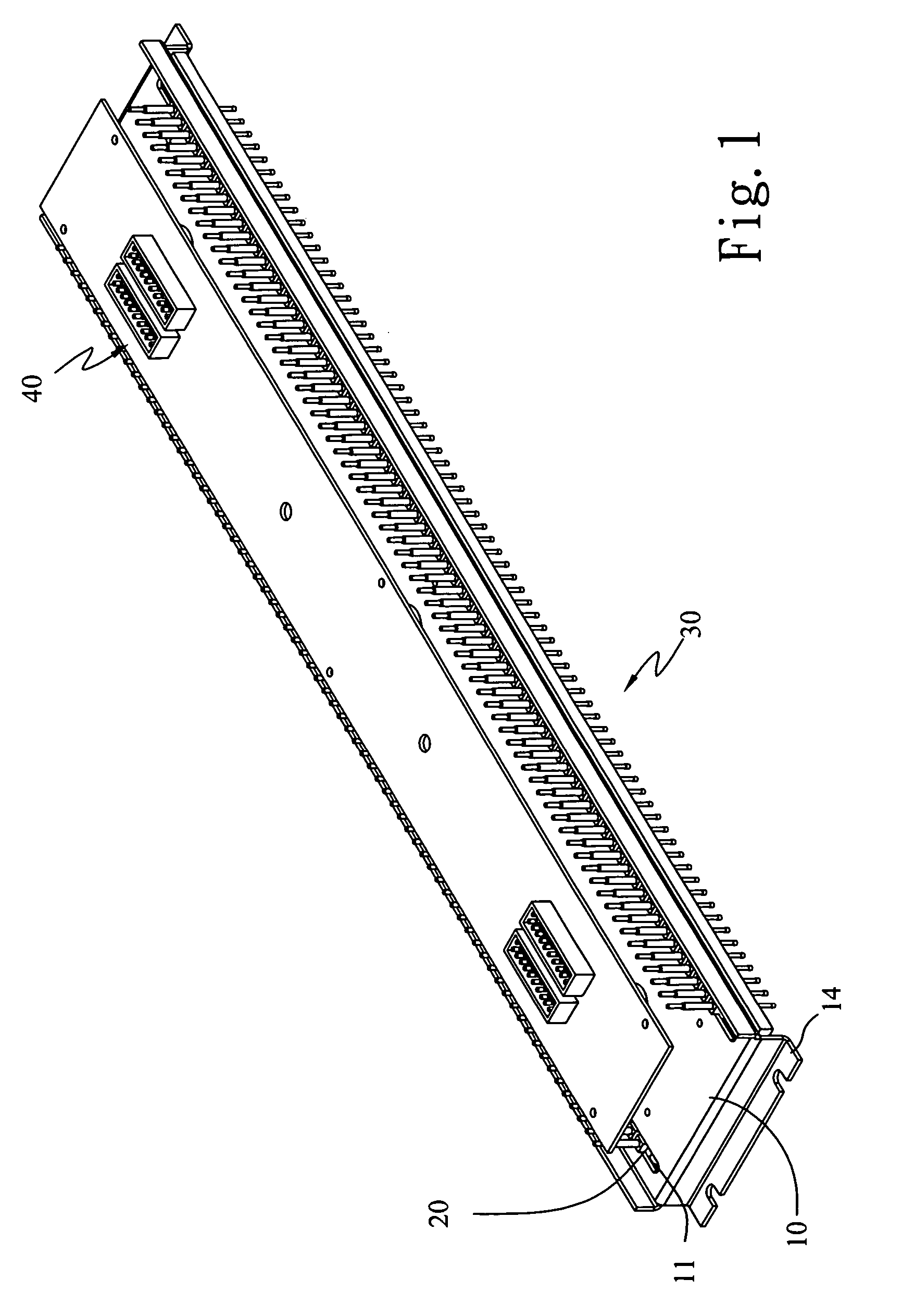
[0018] Please refer to FIG. 1 in which a fuel cell voltage measurement device according to a preferred embodiment of the present invention is shown. As shown, the voltage measurement device includes a main beam 10, a plurality of slides 20, a plurality of retractable probe assemblies 30 in a number corresponding to the slides 20, and a voltage signal collecting unit 40. The main beam 10 is substantially a flat plate having a transverse slot 11 extended across each side thereof and an outward bent side board formed at each end thereof. The slides 20 are received in the slots 11, so as to slidably move along the slots 11 with one-dimensional free mobility. The retractable probe assemblies 30 are correspondingly mounted on the slides 20 to slide along with the slides 20. The voltage signal collecting unit 40 is mounted on a top of the main beam 10 to collect voltage signals collected by the retractable probe assemblies 30.

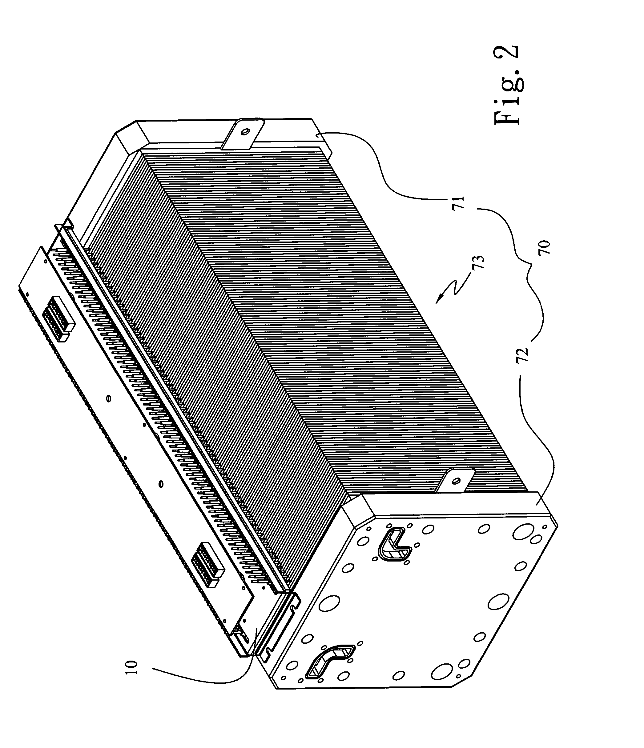
[0019] Please refer to FIG. 2. The voltage measurement device o...


PUM


Abstract

A fuel cell voltage measurement device includes a main beam provided at two sides with a transverse slot each for slidably receiving a plurality of slides therein, and a plurality of retractable probe assemblies separately mounted on the slides to move along with the slides. Therefore, the retractable probe assemblies are applicable to contact with fuel cell bipolar plates having different heights and/or thicknesses, making the voltage measurement device highly practical for use. A voltage signal collecting unit is provided on a top of the main beam for directly collecting the measured voltage signals to obtain a voltage state of the fuel cell.

Description

FIELD OF THE INVENTION [0001] The present invention relates to a fuel cell voltage measurement device, and more particularly to a voltage measurement device adapted to measure the voltage of differently designed and sized fuel cells. BACKGROUND OF THE INVENTION [0002] A proton exchange membrane fuel cell (PEMFC) is also referred to as a high molecular membrane fuel cell, a basic structure of which is a monocell consisting of a membrane electrode assembly (MEA) disposed among two pieces of bipolar plates, a current collector, and two end plates. Two opposite sides divided by the PEMFC membrane electrode assembly are an anode having hydrogen or a rearrangement gas, and a cathode having oxygen or air. At the anode, there is an oxidation reaction, and the cathode a reduction reaction. When the hydrogen at the anode side contacts with a catalyst, which is usually platinum or a platinum alloy, adjoining to the proton exchange membrane, the hydrogen molecule decomposes into hydrogen ion an...

Claims


Application Information

Patent Timeline
IPC IPC(8): G01R31/02
CPCH01M8/04552H01M2008/1095Y02E60/50G01R31/3835G01R31/378
Inventor CHANG, HSU-LINHUANG, JAR-LU
Owner IND TECH RES INST
Why Eureka
Try Eureka