Method for measurement of temperature coefficients of electric circuit components

a technology of temperature coefficient and electric circuit, which is applied in the direction of positive temperature coefficient thermistors, iron-filament ballast resistors, material resistance, etc., can solve the problems of temperature being achieved, measurement time-consuming, measurement time-consuming, etc., and achieve the effect of effective measurement of absolute or relative temperature coefficient or coefficien

Inactive Publication Date: 2007-05-17
MICROBRIDGE TECH INC
View PDF5 Cites 17 Cited by
  • Summary
  • Abstract
  • Description
  • Claims
  • Application Information

AI Technical Summary

Benefits of technology

[0013] The present invention involves the use of local on-chip heating of a particular targeted component or components within a sub-region of a chip, to accomplish effective measurement of absolute or relative temperature coefficient or coefficients, consuming a time period of substantially less than a second.

Problems solved by technology

Since electrical components, devices and circuits must operate in potentially changing surroundings, this is problematic for designers of analog circuits and systems where fine calibration is important for proper function.
At present, this is problematic in the industry.
Because of the large thermal inertia of the oven, such measurements are time consuming, even more so if one desires to make the measurements more than once, for example as part of a burn-in procedure.
Because of the large thermal inertia of the oven, such measurements are time consuming, much more so than adjustment of resistance by any of the currently known or common methods (laser, screwdriver, electrical signals Indeed, Burr-Brown (U.S. Pat. No. 4,356,379) has disclosed a method of heating only a part of a monolithic integrated circuit chip by an on-chip heater.
While this is an advantage over more traditional oven-based methods, the temperature achieved is limited, and the accuracy of the measurement at the elevated temperature is also limited, since the component can only remain at the elevated temperature for a very short time.
At present, there is no way to accomplish a stable measurement at an elevated temperature (e.g. 100° C.

Method used


Image

  • Method for measurement of temperature coefficients of electric circuit components
  • Method for measurement of temperature coefficients of electric circuit components
  • Method for measurement of temperature coefficients of electric circuit components

Examples


Embodiment Construction

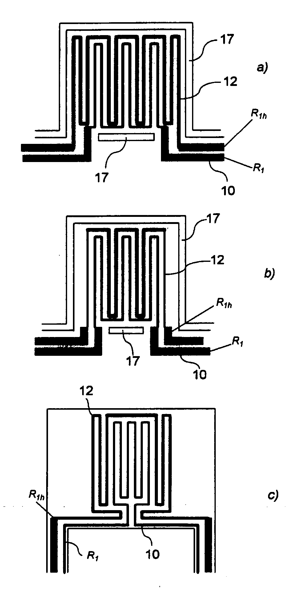
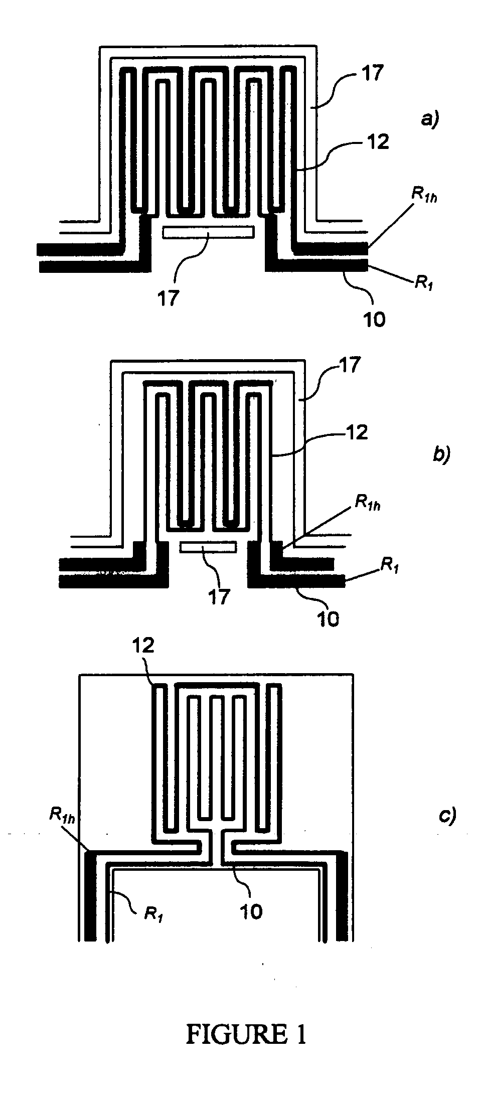
[0023] The concept of a micro-platform or microstructure suspended over a cavity in a substrate (such as a cavity micro-machined in silicon), including electrically-resistive elements for heating and / or sensing, is well-known in the literature (Canadian Microelectronics Corporation Report #IC95-08 September 1995; F. Volklein and H.Baltes, “A Microstructure for Measurement of Thermal Conductivity of Polysilicon Thin Films”, J. Microelectromechanical Systems, Vol. 1, No. 4, December 1992, p. 193, and references therein; Y. C. Tai and R. S. Muller, “Lightly-Doped Polysilicon Bridge as an Anemometer,” Transducers '87, Rec. of the 4th International Conference on Solid-State Sensors and Actuators 1987, pp. 360-363; N. R. Swart and A. Nathan, “Reliability Study of Polysilicon for Micro-hotplates,” Solid State Sensor and Actuator Workshop, Hilton Head, Jun. 13-16, 1994, pp. 119-122.). Micro-platforms with embedded resistive elements are commonly seen in micro-sensor, micro-actuator and micr...


PUM

PropertyMeasurementUnit
temperatureaaaaaaaaaa
resistanceaaaaaaaaaa
sheet resistanceaaaaaaaaaa

Abstract

There is described a method and circuit for determining a temperature coefficient of change of a parameter of an electrical component, the method comprising: providing at least one thermally-isolated micro-platform on a substrate; placing an electrical component on the at least one thermally-isolated micro-platform; heating the electrical component; measuring a parameter value of the electrical component at a plurality of temperatures; and determining the temperature coefficient based on the measured parameter values.

Description

FIELD OF THE INVENTION [0001] The invention relates to the field of measuring temperature coefficients of components. More particularly, it relates to on-chip measurement of the temperature coefficient of an electric circuit component positioned in or on thermally isolated microstructures. BACKGROUND OF THE INVENTION [0002] Temperature coefficients of electronic components are very important in the industrial electronics and microelectronics fields. The electrical properties of all materials may, in general, vary as a function of ambient temperature. Since electrical components, devices and circuits must operate in potentially changing surroundings, this is problematic for designers of analog circuits and systems where fine calibration is important for proper function. Designs must take into account temperature coefficients and their level of uncertainty, and attempt to compensate for absolute and relative variations of components with temperature. [0003] Since they are so important...

Claims


Application Information

Patent Timeline
Patent Type & Authority Applications(United States)
IPC IPC(8): H01C3/04H01C7/04G01N27/14H01C17/232H01C17/26
CPCG01N27/14H01C17/232H01C17/267
Inventor LANDSBERGER, LESLIE M.GRUDIN, OLEGFROLOV, GENNADIY
Owner MICROBRIDGE TECH INC
Why Eureka
Try Eureka