Optical gyro with free space resonator and method for sensing inertial rotation rate

a free space resonator and optical gyro technology, applied in the field of optical gyro systems, can solve the problems of reducing the signal-to-noise ratio, false indication of rotation or inaccurate measurement of rotation rate, and reducing the accuracy of the measurement of rotational ra

Active Publication Date: 2007-05-17
HONEYWELL INT INC
View PDF75 Cites 13 Cited by
  • Summary
  • Abstract
  • Description
  • Claims
  • Application Information

AI Technical Summary

Problems solved by technology

In the RFOG, the glass material of the optical fiber may shift the resonance frequencies of the CW and CCW paths and thus produce a false indication of rotation or inaccurate measurement of rotation rate.
A reflective mirror may be used to circulate the counter-propagating light beams in the coil multiple times but this typically reduces the signal-to-noise ratio from losses generated at the transition from the mirror to the coil.
Additional anomalies that decrease the accuracy of the measurement of the rotational rate may be generated from a non-linear Kerr effect, stimulated Brillouin scattering, and polarization errors.
These error mechanisms are also sensitive to the environment which, for example, gives rise to unwanted temperature sensitivity.
Polarization-induced errors may result from fiber couplers that incidentally couple light into a second polarization mode, either from one optical fiber to an adjacent optical fiber or within the same fiber.
Polarization-induced errors may severely limit the accuracy of the RFOG because determination of the resonance centers for each of the resonance frequencies of the CW and CCW beams directly affects the rotational rate measurement.
In addition to encountering error mechanisms that may affect accuracy, the conventional RFOG may be cost prohibitive for high volume production, particularly for a smaller scale RFOG.
For smaller scale applications, the cost associated with assembling the RFOG generally increases with the increased cost for miniaturizing each component and aligning the miniaturized optical components.

Method used


Image

  • Optical gyro with free space resonator and method for sensing inertial rotation rate
  • Optical gyro with free space resonator and method for sensing inertial rotation rate
  • Optical gyro with free space resonator and method for sensing inertial rotation rate

Examples


Embodiment Construction

[0016] The following detailed description of the invention is merely exemplary in nature and is not intended to limit the invention or the application and uses of the invention. Furthermore, there is no intention to be bound by any theory presented in the preceding background of the invention or the following detailed description of the invention.

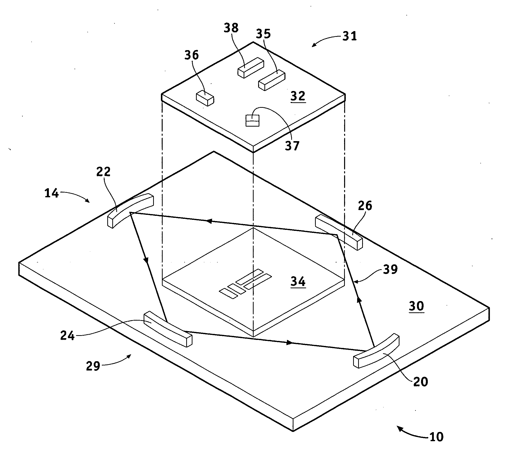
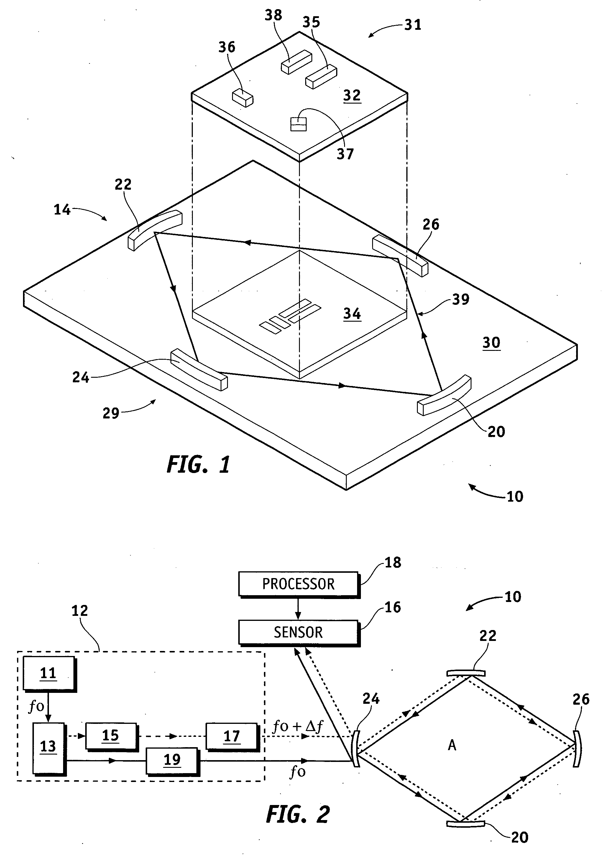
[0017] Referring now to the drawings, FIG. 1 is an exploded view of an optical gyro 10 in accordance with an exemplary embodiment of the present invention. The optical gyro 10 comprises a first substrate 30, a resonator 14 formed on the first substrate 30 and having a closed optical path 39, a signal processing electronics34 (e.g., a signal processor) formed on the first substrate 30, and a second substrate 32 coupled to the signal processing electronics. The first substrate 30, resonator 14, and signal processing electronics 34 are collectively referred to as a first optical bench 29. The substrates 30, 32 may be silicon, silicon-on-insul...


PUM


Abstract

Methods and apparatus are provided for a low cost optical gyro with a free space closed optical path. A ring resonator comprises a substrate and reflectors formed or placed on the substrate. The reflectors comprise a closed optical path and are configured to direct each of first and second light beams in a different counter-propagating direction in the closed optical path. Each of the first and second light beams frequencies are tuned to the resonance frequency of the resonator in the direction of propagation for which the light beam is circulating in the closed optical path.

Description

FIELD OF THE INVENTION [0001] The present invention generally relates to gyro systems, and more particularly relates to rotational sensors for use in navigation systems and attitude control. BACKGROUND OF THE INVENTION [0002] Gyros have been used to measure rotation rates or changes in angular velocity about an axis of rotation. A basic conventional fiber optic gyro (FOG) includes a light source, a beam generating device, and a coil of optical fiber coupled to the beam generating device that encircles an area. The beam generating device transmits light beams into the coil that propagate in a clockwise (CW) direction and a counter-clockwise (CCW) direction along the core of the optical fiber. Many FOGs utilize glass-based optical fibers that conduct light along a solid glass core of the fiber. The two counter-propagating (e.g., CW and CCW) beams experience different pathlengths while propagating around a rotating closed optical path, and the difference in the two pathlengths is propo...

Claims


Application Information

Patent Timeline
Patent Type & Authority Applications(United States)
IPC IPC(8): G01C19/66
CPCG01C19/726
Inventor SANDERS, GLEN A.HUGHES, GRENVILLEKEYSER, THOMASSTRANDJORD, LEE K.
Owner HONEYWELL INT INC
Why Eureka
Try Eureka