Polarization mode dispersion compensator and polarization mode dispersion compensating method

Inactive Publication Date: 2007-05-17
FUJITSU LTD
View PDF4 Cites 23 Cited by
  • Summary
  • Abstract
  • Description
  • Claims
  • Application Information

AI Technical Summary

Benefits of technology

[0012] It is an object of the present invention to provide a PMD compensator and a PMD compensating method which realize practical implementation of adaptive step size control. In particular, a fast method is described to adaptively optimize the step size with which the parameters applied on the polarization controller are changed for each feedback loop.
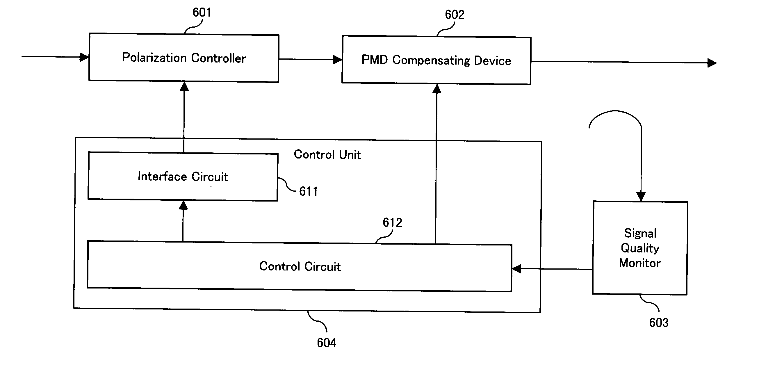
[0013] A polarization mode dispersion compensator according to the present invention comprises a polarization controller, a compensating device, a signal quality monitor, and a control unit. The polarization controller transforms polarization of an input optical signal and the compensating d

Problems solved by technology

The reach of high bit-rate optical transmission systems becomes limited by PMD.
A problem arises due to the fact that the amount of introduced distortion (required for testing the optimum control point in the trial and error method) depends not only on the amount of applied parameter changes but also on the angular distance between the input polarization and the eigenaxis of the polarization controller.
Dithering the feedback parameters of the polarization controller with fixed step sizes is either too slow to track changing PMD conditions (small step size) or does not provide optimum compensation performance (large step size).
Due to the limited amount of applicable parameter changes, the PMD of the transmission fiber may change faster than the PMD compensator is able to track when a fast disturbance arises.
Otherwise an unacceptable amount of signal distortion would be introduced by the PMD compensator.
On the other hand, the limited amount of applicable parameter change leads to little or even no change of the systems (transmission fiber plus PMD compensator) polarization mode dispersion in cases the input polariza

Method used


Image

  • Polarization mode dispersion compensator and polarization mode dispersion compensating method
  • Polarization mode dispersion compensator and polarization mode dispersion compensating method
  • Polarization mode dispersion compensator and polarization mode dispersion compensating method

Examples


Embodiment Construction

[0023] Hereinafter, preferred embodiments according to the present invention will be described in detail by referring to the drawings.

[0024] In the embodiments, the past DOP variations (DOP history) caused by the applied control voltages to the polarization controller are evaluated. Depending on whether the past DOP variance is above or below a certain threshold, corresponding control parameters (which are to be applied in the next step) are decreased or increased. Applying this control method, too big steps which lead to decreased compensation performance as well as too small steps which lead to dangerously reduced response time are effectively avoided. In order to further enhance the response time (tracking capability in cases of fast PMD fluctuation due to e.g. fiber touching), the control method includes the monitoring of control steps leading to wrong directions, i.e. directions causing a decrease of PMD compensation instead of an improved compensation. By this method, the num...


PUM


Abstract

An amount of change of a control signal applied to a polarization controller in a polarization mode dispersion compensator is determined for each feedback loop by evaluating degree of polarization response in past feedback loops.

Description

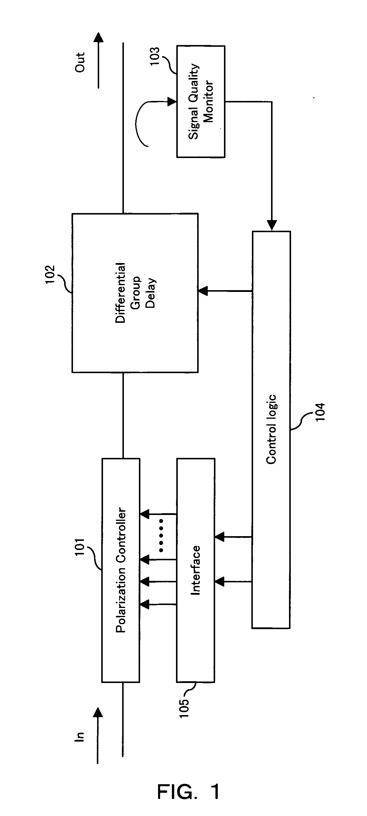
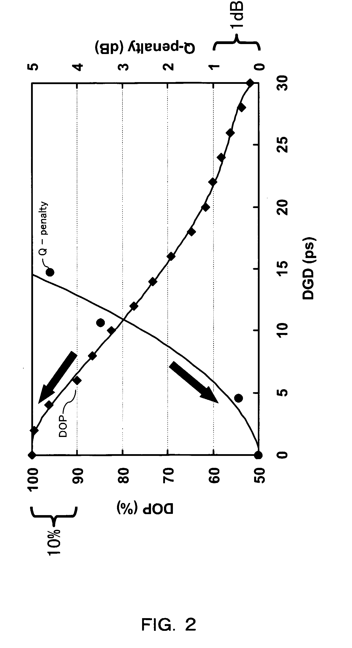
TECHNICAL FIELD [0001] The present invention relates to a compensation of polarization mode dispersion (PMD) for high bit-rate optical data transmission. BACKGROUND ART [0002] The reach of high bit-rate optical transmission systems becomes limited by PMD. The amount of PMD (expressed in terms of differential group delay (DGD) for the first order PMD) and also the orientation (expressed in terms of the principal states of polarization) fluctuate statistically with environmental changes like temperature. Therefore, a compensating device needs to be adaptive. Several solutions have been presented. As a general design, a polarization controller followed by a PMD compensating element is used. [0003]FIG. 1 shows such a PMD compensator. The PMD compensator shown in FIG. 1 comprises polarization controller 101, DGD element 102 (fixed or variable), signal quality monitor 103, control logic 104, and interface 105. The signal quality monitor 103 provides feedback to the control logic 104. The ...

Claims


Application Information

Patent Timeline
IPC IPC(8): H04B10/00H04B10/2507G02F1/01H04B10/07H04B10/2569
CPCH04B10/2569
Inventor RASMUSSEN, JENS C.ISOMURA, AKIHIKOISHIKAWA, GEORGE
Owner FUJITSU LTD
Why Eureka
Try Eureka