Systems and methods for managing fluids using a liquid ring pump

a technology of liquid ring pump and liquid ring pump, which is applied in the direction of positive displacement liquid engine, process and machine control, instruments, etc., can solve the problems of uncertainty in etch rate and chemical management system inability to adequately control a plurality of process parameters

Inactive Publication Date: 2007-05-17
AIR LIQUIDE ELECTRONICS US LP +1
View PDF55 Cites 6 Cited by
  • Summary
  • Abstract
  • Description
  • Claims
  • Application Information

AI Technical Summary

Benefits of technology

[0011] One embodiment provides a vacuum pump system including a vacuum line fluidly coupled to at least one of a plurality of fluid outlets of a processing station; a liquid ring pump having a suction port coupled to the vacuum line to receive an incoming multiphase stream formed from one or more fluids removed from the plurality of fluid outlets; a tank coupled to an exhaust port of the liquid ring pump and comprising one or more devices configured for removing liquid from a multiphase stream output by the liquid ring pump through the exhaust port; and a pressure control system disposed in the vacuum line upstream from the liquid ring pump, wherein the pressure control system is configured to maintain a target pressure in the vacuum line according to a desired pressure in the processing station.
[0012] Another embodiment provides a vacuum pump system including a vacuum line fluidly coupled to at least one of a plurality of fluid outlets of a processing station; a liquid ring pump having a suction port coupled to the vacuum line to receive an incoming multiphase stream formed from one or more fluids removed from the plurality of fluid outlets; a tank coupled to an exhaust port of the liquid ring pump and comprising one or more devices configured for removing liquid from a multiphase stream output by the liquid ring pump through the exhaust port; and a coolant source for injecting a cooling fluid into the incoming multi-phase stream prior to the multiphase stream being input to the liquid ring pump, the cooling fluid having a temperature sufficient to condense liquid from the multiphase stream.
[0013] Another embodiment provides a vacuum pump system including a vacuum line fluidly coupled to at least one of a plurality of fluid outlets of a processing station; a liquid ring pump having a suction port coupled to the vacuum line to receive an incoming multiphase stream formed from one or more fluids removed from the plurality of fluid outlets; a tank coupled to an exhaust port of the liquid ring pump and comprising one or more devices configured for removing liquid from a multiphase stream output by the liquid ring pump through the exhaust port; and a chemical concentration control system. The chemical concentration control system is configured to: monitor a concentration of a sealant fluid contained in the tank and fed to the liquid ring pump for the operation of the liquid ring pump; and selectively adjust a concentra...

Problems solved by technology

In either case, accurate mixing of reagents at desired ratios is particularly important because variations in concentration of the chemicals detrimentally affect process performance.
For example, failure to maintain specified concentrations of che...

Method used


Image

  • Systems and methods for managing fluids using a liquid ring pump
  • Systems and methods for managing fluids using a liquid ring pump
  • Systems and methods for managing fluids using a liquid ring pump

Examples


Embodiment Construction

[0028] Embodiments of the present invention provide methods and chemical management systems for controlling various aspects of fluid delivery and / or recovery.

systems Overview

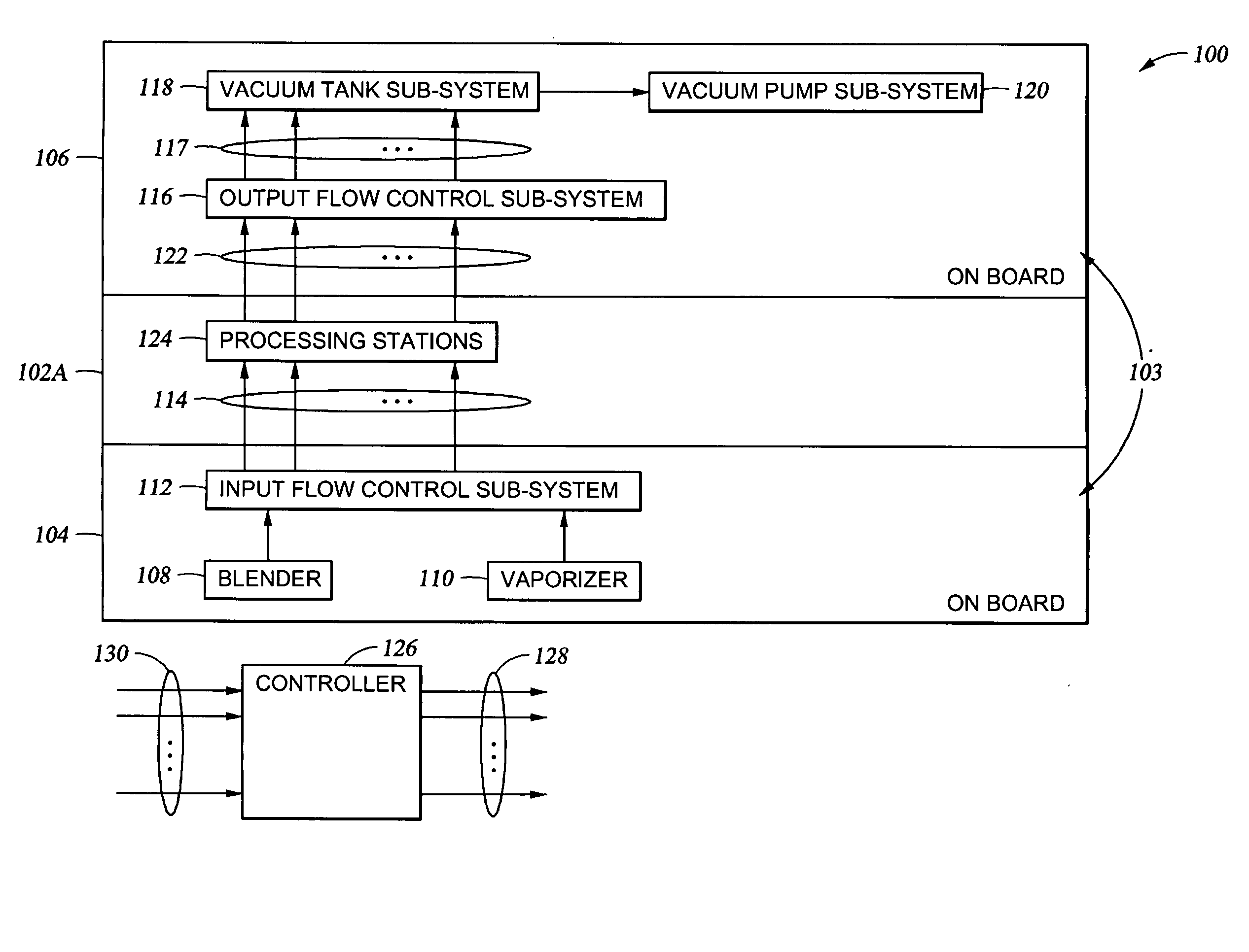
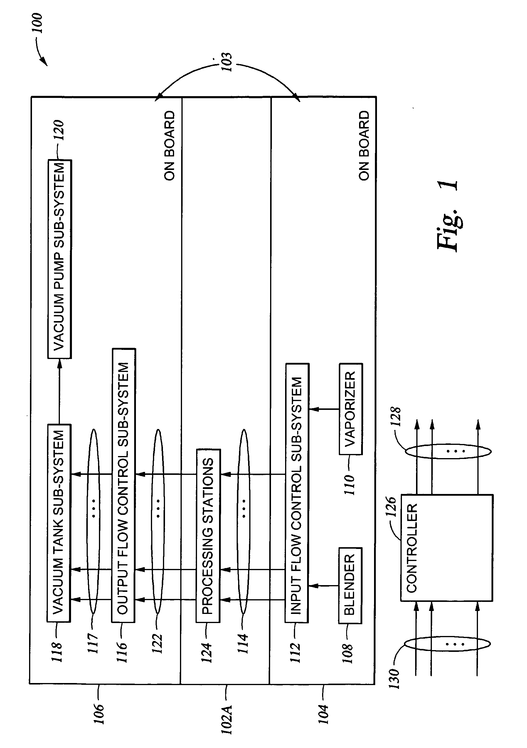
[0029]FIG. 1 shows one embodiment of a processing system 100. Generally, the system 100 includes a processing chamber 102 and a chemical management system 103. According to one embodiment, the chemical management system 103 includes an input subsystem 104 and an output subsystem 106. It is contemplated that any number of the components of the subsystems 104, 106 may be located onboard or off-board, relative to the chamber 102. In this context, “onboard” refers to the subsystem (or component thereof being integrated with the chamber 102 in the Fab (clean room environment), or more generally with a processing tool of which the chamber 102 is a part; while “off-board” refers to the subsystem (or component thereof) being separate from, and located some distance away from, the chamber 102 (or tool, generally). In ...


PUM

PropertyMeasurementUnit
Temperatureaaaaaaaaaa
Pressureaaaaaaaaaa
Concentrationaaaaaaaaaa

Abstract

Methods and systems for chemical management. In one embodiment, a blender is coupled to a processing system and configured to supply an appropriate solution or solutions to the system. Solutions provided by the blender are then reclaimed from the system and subsequently reintroduced for reuse. The blender may be operated to control the concentrations of various constituents in the solution prior to the solution being reintroduced to the system for reuse. Some chemicals introduced to the system may be temperature controlled. A back end vacuum pump subsystem separates gases from liquids as part of a waste management system.

Description

CROSS-REFERENCE TO RELATED APPLICATIONS [0001] This application claims the benefit under 35 U.S.C. § 119(e) to provisional application No. 60 / 801,913, filed May 19, 2006, the entire contents of which are incorporated herein by reference. This application also claims priority from and is a continuation-in-part of U.S. Patent Application Ser. No.______, filed Sep. 18, 2006 (Attorney Docket No. Serie 7132), which claims priority from U.S. Provisional Patent Application Ser. No. 60 / 720,597, entitled “Point of Use Process Control Blender,” and filed Sep. 26, 2005. This application is further a continuation-in-part of U.S. patent application Ser. No. 11 / 107,494, filed Apr. 15, 2005, which is a continuation-in-part of U.S. patent application Ser. No. 10 / 939,570, filed Sep. 13, 2004, which is a divisional application of U.S. patent application Ser. No. 09 / 468,411, filed Dec. 20, 1999 (now U.S. Pat. No. 6,799,883), which is a continuation-in-part of U.S. patent application Ser. No. 09 / 051,30...

Claims


Application Information

Patent Timeline
IPC IPC(8): F04B49/00
CPCF04C19/001H01L21/67017
Inventor URQUHART, KARL J.GUARNERI, GEORGESMARC, JEAN-LOUISFANJAT, NORBERTLANGELLIER, LAURENTCOLIN, CHRISTOPHE
Owner AIR LIQUIDE ELECTRONICS US LP
Why Eureka
Try Eureka