Method for Producing a Subminiature "Micro-Chip" Oxygen Sensor for Control of Internal Combustion Engines or Other Combustion Processes, Oxygen Sensor and an Exhaust Safety Switch

a technology of oxygen sensor and microchip, which is applied in the direction of electrical control, instruments, material electrochemical variables, etc., can solve the problems of high cost of sensors, complex circuitry, and inability to meet the requirements of the application, so as to reduce the resistance of the semiconducting portion of the element and minimize the temperature effect

Active Publication Date: 2011-08-04
KERDEA TECH
View PDF28 Cites 19 Cited by
  • Summary
  • Abstract
  • Description
  • Claims
  • Application Information

AI Technical Summary

Benefits of technology

[0013]Each singulated chip element is then placed into an assembly, which is secured onto an exhaust system in such a way as to expose the sensing portion of the chip to exhaust gases. A voltage is applied to a heater circuit on the chip to bring the element to a temperature sufficient to activate the sensor. The resistance of the semiconducting portion of the element decreases with increased temperature, and either increases as it is exposed to higher levels of oxygen or decreases with increased oxygen, depending on the semiconducting material employed. By maintaining the element at an elevated temperature (above about 600° C.) the temperature effect is minimized and the condition of the exhaust gas can be determined by the step change in resistance at stoichiometry.

Problems solved by technology

However, these sensors in their present state are cost prohibitive for a vast majority of global applications.
Unfortunately, these sensors are very expensive, have complicated circuitry, and the size reduction potential is limited due to the need to have enough charge carriers to generate a signal.
As such, they are therefore not suitable for the small engine market.

Method used


Image

  • Method for Producing a Subminiature "Micro-Chip" Oxygen Sensor for Control of Internal Combustion Engines or Other Combustion Processes, Oxygen Sensor and an Exhaust Safety Switch
  • Method for Producing a Subminiature "Micro-Chip" Oxygen Sensor for Control of Internal Combustion Engines or Other Combustion Processes, Oxygen Sensor and an Exhaust Safety Switch
  • Method for Producing a Subminiature "Micro-Chip" Oxygen Sensor for Control of Internal Combustion Engines or Other Combustion Processes, Oxygen Sensor and an Exhaust Safety Switch

Examples


Embodiment Construction

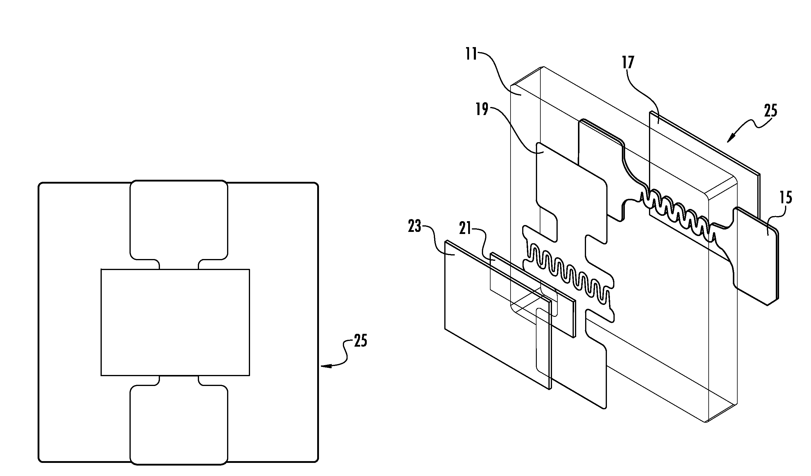
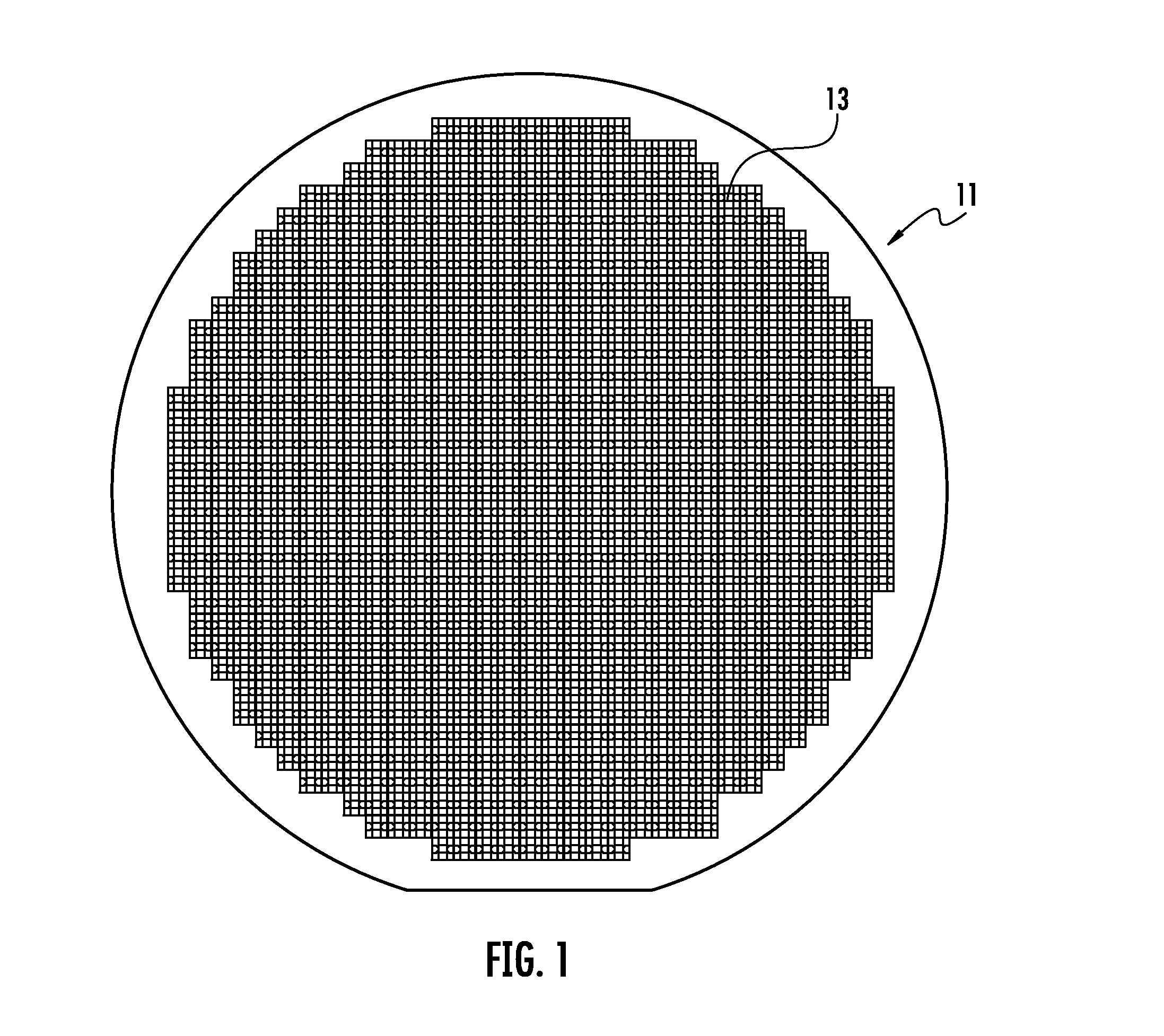
[0037]As shown in FIG. 1, for purposes of illustration only and not limitation, the present invention includes a thin, typically about 0.005″ to about 0.015″ thick ceramic substrate or wafer 11 made primarily of aluminum oxide in a ratio of about 94% to about 99.5% by weight, or other suitable dielectric material upon which multiple elements may be produced by first applying thin heater patterns composed of platinum, palladium, a combination thereof, and / or other suitable materials, and placed thereon. Such suitable dielectrics include but are not limited to boron nitride, steatite (magnesium silicate), zirconium toughened alumina (ZTA), etc. . . .

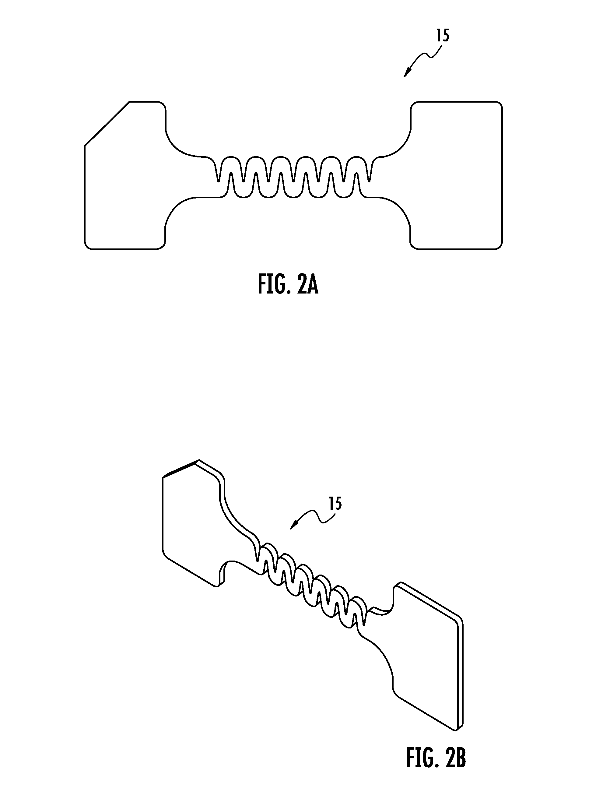
[0038]The heater patterns, as shown in FIG. 2, can be applied using physical vapor deposition (electron beam or sputtering) or electroless plating, then masking using photolithography techniques followed by chemical etching. Alternatively, the heater pattern 15 can be applied by first masking the substrate using photolithography techniques...


PUM

PropertyMeasurementUnit
temperatureaaaaaaaaaa
voltageaaaaaaaaaa

Abstract

A method of making a sub-miniature “micro-chip” oxygen sensor is provided where multiple sensor elements are applied to a dielectric ceramic substrate consisting of a heater pattern, followed by a dielectric layer. Intermeshing electrodes are then applied either over the heater pattern/dielectric layers or on the opposite side of the substrate. The space between the intermeshing electrodes is filled with an n-type or p-type high temperature semiconductor which is covered by a porous protection layer. After singulation (dicing), the sensor element is assembled having conductors applied to the contact pads on the element and is packaged in an assembly for introduction to the exhaust stream of a combustion process. A large step-wise change in the resistance of the element takes place as a result of changes in oxygen content in the exhaust whereby one can determine if the exhaust is rich or lean for use in an engine management or combustion management systems for emissions control. A circuit is proposed to convert the change in resistance to a voltage signal to be used for control algorithms in engine or combustion control. Utilizing multiple units of the device for individual cylinder control of multi-cylinder engines is described. A method of using one embodiment of the invention for use as a safety switch is also revealed.

Description

CROSS REFERENCE TO RELATED APPLICATIONS[0001]This application is related to and claims priority to U.S. Provisional Application Ser. No. 61 / 295,487, filed Jan. 29, 2010, the disclosure of which is specifically incorporated by reference herein.FIELD OF THE INVENTION[0002]The present invention relates to oxygen sensors for sensing exhaust gases in an internal combustion engine or in any combustion process where control of the air-fuel ratio is desired. Of particular usefulness is the use of the sensors for control of small spark ignition engines such as those used in motorcycles, ATVs, recreational marine applications and unmanned air vehicles. In addition, the sensor is also suitable for individual cylinder control in multi-cylinder engines and hybrid engines for automotive and off-road applications. This invention may also be used as a safety device to trigger an alarm and / or disable combustion processes that produce rich exhaust gasses in enclosed spaces to prevent adverse conditio...

Claims


Application Information

Patent Timeline
Patent Type & Authority Applications(United States)
IPC IPC(8): G01N27/30H01L21/04
CPCF01N2560/025G01M15/104G01N27/4067F01N3/2026F01N11/002F01N2560/20F02D41/042
Inventor FOSAAEN, KEN ERVIN
Owner KERDEA TECH
Why Eureka
Try Eureka