Radio frequency grounding apparatus

Inactive Publication Date: 2007-05-24
CELETECH SEMICON
View PDF5 Cites 7 Cited by
  • Summary
  • Abstract
  • Description
  • Claims
  • Application Information

AI Technical Summary

Benefits of technology

[0009] The objective of the present invention is to provide an RF grounding apparatus, and more particularly to an RF grounding apparatus using a clamp and a flexible conductive sheet to form a grounding path. The RF grounding apparatus utilizes the surface contact provided by the clamp and the flexible connection provided by the flexible conductive sheet to prevent arcing generated at a bo

Problems solved by technology

Once the contact resistance increases, the RF energy passing through is apt to cause arcing, which results in high reflected power, unstable process conditions and oxidation of the bottom end of the RF grounding rod 13.
The contact resistance deteriorated by the oxidation will increase the possibility of arcing.
Accordingly, such a vicious c

Method used


Image

  • Radio frequency grounding apparatus
  • Radio frequency grounding apparatus
  • Radio frequency grounding apparatus

Examples


Example

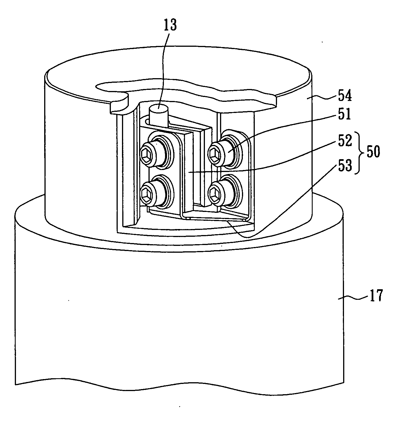
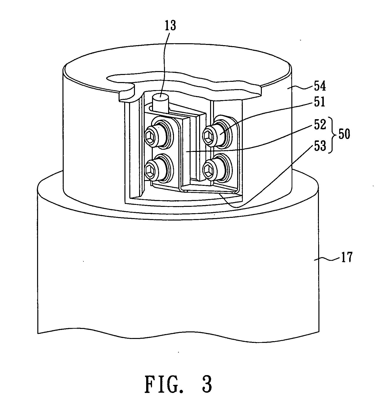
[0017]FIG. 3 shows one embodiment of the applications of the RF grounding apparatus of the present invention, which is upside-down for easy understanding. The RF grounding apparatus 50 is applied to an RF grounding rod 13 of a plasma reaction chamber. FIG. 4 shows an exploded view of the RF grounding apparatus 50. The RF grounding apparatus 50 comprises a clamp 52 and a flexible conductive sheet 53. The clamp 52 comprises two side portions 523 and an arced portion 524, which form a hollow portion to accommodate the bottom of the RF grounding rod 13. The flexible conductive sheet 53 is a U-like structure, which comprises two side plates 528 and a middle plate 527 connecting the two side plates 528. The thickness of the flexible conductive sheet, which is a metal sheet in the current embodiment, is from 0.1 mm to 5 mm. Each of the two side portions has a plurality of threaded holes 525 (two threaded holes in each side portion 523 in the current embodiment, and another two threaded hol...


PUM

PropertyMeasurementUnit
Lengthaaaaaaaaaa
Lengthaaaaaaaaaa
Electrical resistanceaaaaaaaaaa

Abstract

The radio frequency (RF) grounding apparatus of the present invention uses a clamp to clamp an RF grounding rod by surface contact to improve the connection stability. The clamp is connected to a flexible conductive sheet to form a grounding path to avoid the arcing generated by the bottom part (e.g., a heater) of a traditional plasma reaction chamber and to avoid breakage of the ceramic surface of the bottom part of the plasma reaction chamber, which would be caused by the RF grounding rod due to thermal expansion. The heater of the plasma reaction chamber, which is equipped with the RF grounding apparatus of the present invention, exhibits an extended lifetime. The top of the RF grounding rod is fixed to an RF mesh, and the RF grounding rod extends downward. The bottom of the RF grounding rod is clamped firmly and electrically by the clamp. The flexible conductive sheet connects the clamp and the grounding base of the plasma reaction chamber to form a grounding path.

Description

RELATED U.S. APPLICATIONS [0001] Not applicable. STATEMENT REGARDING FEDERALLY SPONSORED RESEARCH OR DEVELOPMENT [0002] Not applicable. REFERENCE TO MICROFICHE APPENDIX [0003] Not applicable. FIELD OF THE INVENTION [0004] The present invention relates to a radio frequency (RF) grounding apparatus, and more particularly to an RF grounding apparatus using a clamp and a flexible conductive sheet to form a grounding path, which is especially suitable for a plasma reaction chamber. BACKGROUND OF THE INVENTION [0005] The deposition of dielectric material is one of the important steps in the semiconductor manufacturing process. Dielectric material is used as an intermetal dielectric (IMD) to isolate the adjacent metal lines electrically, as a passivation layer to protect the circuits on a chip from moisture and metal ions, and as a dielectric anti-reflection coating (DARC) in the lithography process. FIG. 1 illustrates a commonly used dielectric deposition system 1, which comprises a react...

Claims


Application Information

Patent Timeline
IPC IPC(8): C23F1/00C23C16/00
CPCC23F4/00H01J37/32174H01J37/32577
Inventor HO, CHANG SUNG
Owner CELETECH SEMICON
Why Eureka
Try Eureka